Auxiliary system for mounting optical camera in deep-embedded mode

An optical camera and installation assistance technology, which is applied in the field of high-reliability installation assistance systems, can solve problems such as the difficulty of camera installation and disassembly, easy collision, extrusion, and camera quality impact, so as to save installation time, reduce operating intensity, The effect of easy operation

Active Publication Date: 2018-01-09
BEIJING INST OF SPACECRAFT ENVIRONMENT ENG
View PDF3 Cites 4 Cited by
  • Summary
  • Abstract
  • Description
  • Claims
  • Application Information

AI Technical Summary

Problems solved by technology

[0002] The optical camera is an important payload of a remote sensing satellite. Due to the heavy weight of the camera (usually 500kg to 2000kg), in order to reduce the height of the center of mass of the entire satellite, the optical camera is often embedded in the interior of the payload cabin with a large depth. For example, see figure 1 , figure 1 It is a schematic diagram of the installation state of the camera embedded in the load compartment in the prior art; due to the limitations of the satellite configuration and other aspects, the distance between the camera and the star is small, which brings greater difficulty to the installation and removal of the camera
The installation of the optical camera needs to be carried out in the form of hoisting. At present, the minimum distance between some models of cameras and the load cabin is only 5mm. The installation risk is high, and accidents such as bumping and extrusion are prone to occur during the installation process. There are many optical sensitive components in the optical camera, and accidents such as bumping and extrusion have a great impact on the quality of the camera.

Method used


Image

  • Auxiliary system for mounting optical camera in deep-embedded mode
  • Auxiliary system for mounting optical camera in deep-embedded mode
  • Auxiliary system for mounting optical camera in deep-embedded mode

Examples


Embodiment Construction

[0024] Specific embodiments of the present invention will be described in detail below in conjunction with the accompanying drawings, but these are only exemplary and not intended to limit the scope of protection thereof.

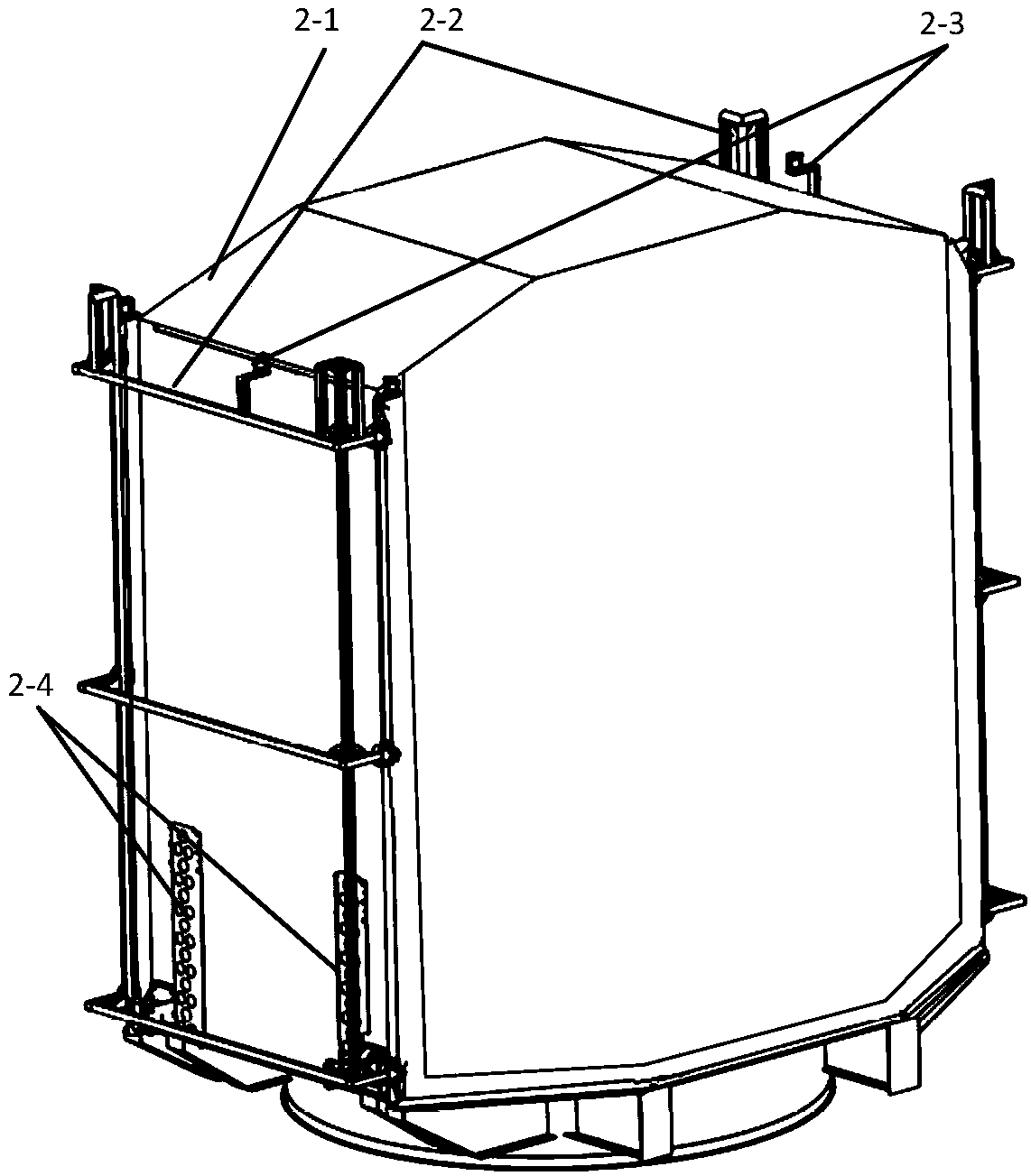
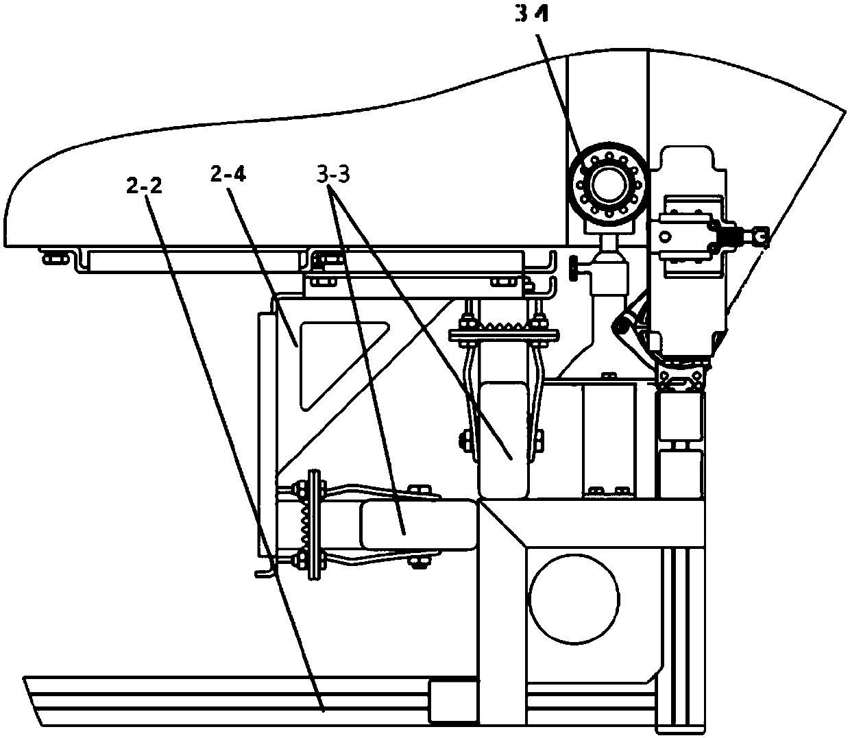
[0025] see figure 2 , figure 2 It shows the structural diagram of the large-depth embedded installation auxiliary system of optical camera of the present invention; the large-depth embedded installation auxiliary system of optical camera of the present invention includes two parts: a mechanical guide device and a real-time monitoring system arranged inside the load compartment cabin body, and the camera The main body 2-1 is arranged in the mechanical guiding device, and the mechanical guiding device includes 4 guide roller sets and 2 sets of guide roller tracks 5-1, 5-2, and the guide roller tracks are illustrated in Figure 5 Among them, each group of guide rollers includes two parallel guide rollers erected in the load cabin body; the guide rollers are...


PUM


Abstract

The invention discloses an auxiliary system for mounting an optical camera in a deep-embedded mode. The auxiliary system comprises two parts of a mechanical guiding device and a real-time monitoring system which are arranged inside a cabin body of a load cabin. The mechanical guiding device is in fastened connection with the load cabin through a load cabin hole position and guides the camera to beslowly embedded in the cabin body of the load cabin through a guiding roller set. The real-time monitoring system comprises a position and pose positioning part and a position and pose monitoring part for monitoring the safe distance between the camera and a satellite body by 360 degrees. Through an active and passive combination mounting process, the operation intensity of manual holding and gapobserving difficulty can be lowered, mounting risks are reduced, and the mounting time is saved.

Description

technical field [0001] The invention belongs to the technical field of spacecraft ground support equipment, and in particular relates to an auxiliary system for highly reliable installation of spacecraft optical payloads. Background technique [0002] The optical camera is an important payload of a remote sensing satellite. Due to the heavy weight of the camera (usually 500kg to 2000kg), in order to reduce the height of the center of mass of the entire satellite, the optical camera is often embedded in the interior of the payload cabin with a large depth. For example, see figure 1 , figure 1 It is a schematic diagram of the installation state of the camera embedded in the payload cabin in the prior art; due to the limitations of the satellite configuration and other aspects, the distance between the camera and the star is small, which brings great difficulty to the installation and disassembly of the camera. The installation of the optical camera needs to be carried out in ...

Claims


Application Information

Patent Timeline
Patent Type & Authority Applications(China)
IPC IPC(8): B64G1/66
Inventor 徐奕柳张彬易旺民郑为志张立建许凯张伟马明阳刘广通李浩张延磊郭涛王伟尹成爽梁寅付英莲
Owner BEIJING INST OF SPACECRAFT ENVIRONMENT ENG
Why Eureka
Try Eureka