Concrete beam damage monitoring system and monitoring method

A technology for concrete beams and monitoring systems, applied to measuring devices, material analysis through electromagnetic means, instruments, etc., can solve the problems of difficult monitoring work and structural health monitoring, and achieve high power, simple structure, sensitive effect

Pending Publication Date: 2018-01-09
CHANGAN UNIV +1
View PDF5 Cites 15 Cited by
  • Summary
  • Abstract
  • Description
  • Claims
  • Application Information

AI Technical Summary

Problems solved by technology

For some difficult-to-reach places of the structure, the monitoring work is difficult to carry out, and the real structural health monitoring cannot be realized

Method used


Image

  • Concrete beam damage monitoring system and monitoring method
  • Concrete beam damage monitoring system and monitoring method
  • Concrete beam damage monitoring system and monitoring method

Examples


Embodiment

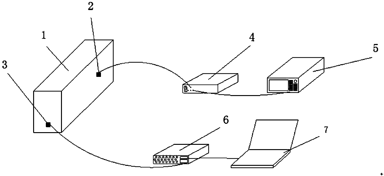
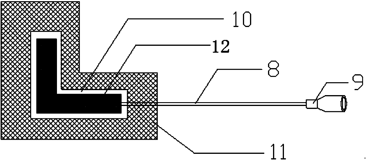
[0092] Such as Figure 4 As shown, the intelligent aggregate is embedded in the key position of the concrete beam. The piezoelectric ceramic sensor is connected to the signal acquisition system through the shielded wire. The signal acquisition system is connected to the computer analysis system. The signal function generator is connected to the piezoelectric ceramic driver through the high voltage signal amplifier. connect,

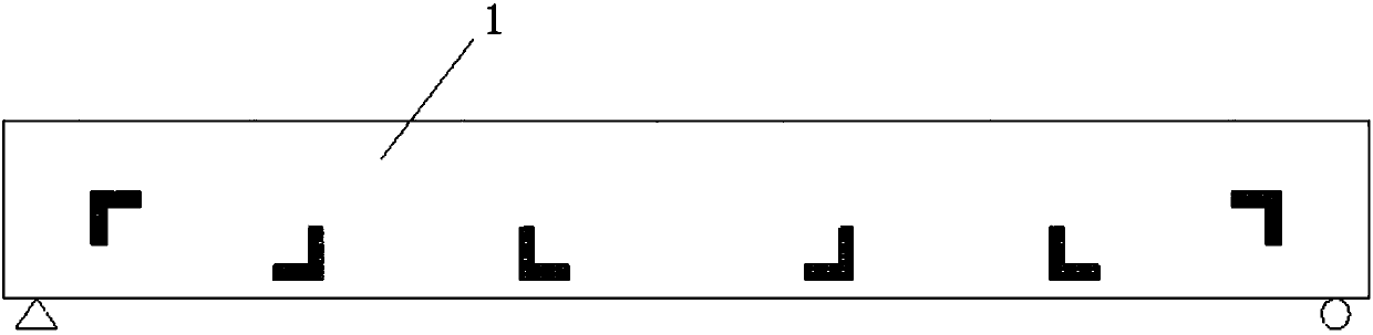
[0093] The cross-sectional size of the concrete beam is 0.2m×0.4m, and the length is 3m. The prefabricated intelligent aggregates SA1, SA2, SA3, SA4, SA5, and SA6 are embedded in the concrete beam in order from left to right. method effectiveness, before pouring concrete, a thin foam board was pasted in the cracked area to simulate the damaged area,

[0094] a. The distance between intelligent aggregates is 0.5m, and the distance between intelligent aggregate SA1 and intelligent aggregate SA6 is 0.25m from the end face of the concrete beam. The sequence ...


PUM


Abstract

The invention discloses a concrete beam damage monitoring system and a monitoring method. The method comprises the following steps: presetting a set of two intelligent aggregates into a to-be-detectedconcrete beam; respectively using the two intelligent aggregates as a piezoelectric ceramic driver and a piezoelectric ceramic sensor; exciting the piezoelectric ceramic driver through a high pressure amplifier by utilizing a signal generated by a signal function generator; analyzing the collected signal by a signal processing module connected with the piezoelectric ceramic sensor, thereby acquiring a peak signal; comparing the peak signal with an initial value of the signal emitted by the signal function generator, thereby acquiring the interior condition of the to-be-detected concrete beam.The monitoring system has the advantages of sensitive sensing, safety, reliability and wide measuring scope. The monitoring system has a simple structure and high power, is suitable for monitoring various slant cracks and crossing cracks generated in the concrete beams at different shear span ratios and is capable of realizing the functions of horizonal and vertical bidirectional motivation and signal collection.

Description

technical field [0001] The invention belongs to the field of health monitoring of civil engineering structures, in particular to a concrete beam damage monitoring system and a monitoring method. Background technique [0002] The concrete girder bridge structure occupies an important position in the bridge structure. However, due to the joint influence of the load and various sudden factors, it has been facing the problem of structural damage since the beginning of service, such as vertical cracks in the concrete beam span and different shear forces. Various oblique cracks in the shear-bending area of ​​concrete beams with a span ratio, when the damage accumulates to a certain extent, will cause the attenuation of the structural resistance, seriously reduce the safety, applicability and durability of the structure, and in extreme cases will cause the entire damage to the structure. [0003] In addition, taking appropriate reinforcement measures for the damaged beam bridge st...

Claims


Application Information

Patent Timeline
Patent Type & Authority Applications(China)
IPC IPC(8): G01N27/00
Inventor 刘来君张筱雨陈冰洋张柳煜宋钢兵霍林生
Owner CHANGAN UNIV
Why Eureka
Try Eureka