Arc extinguishing load switch

A load switch and arc extinguishing technology, applied in electrical switches, high-voltage/high-current switches, high-voltage air circuit breakers, etc., can solve the problems of roughness, large size, poor arc extinguishing performance, etc., achieve reliable conductive connection, and the overall structure is simple , Improve the effect of arc extinguishing efficiency

Active Publication Date: 2021-02-05
XIAMEN HUADIAN SWITCHGEAR
View PDF7 Cites 0 Cited by
  • Summary
  • Abstract
  • Description
  • Claims
  • Application Information

AI Technical Summary

Problems solved by technology

Although the vacuum type structure is convenient, such as the invention patent literature of China Authorized Announcement No. CN 101800137B, which discloses this technology, its cost is very high and there is no isolation fracture; The patent literature discloses this technology, but SF6 gas is a non-environmental gas, and its development and application are limited; the traditional compressed gas and gas generating products are affected by the arc extinguishing performance, and the volume is relatively large, which cannot be miniaturized. Just disclose a kind of safe compressed air type air load switch as the utility model patent document of Chinese authorization announcement CN 2256584 Y
To sum up, most of the current load switches use the above methods alone for arc extinguishing, and fail to combine the related arc extinguishing structures skillfully and organically, and the overall structure is relatively clumsy; therefore, the existing extinguishing The arc extinguishing ability of the arc switch needs to be further improved, and the structure needs to be further optimized
[0004] In addition, the current designs for the compressed air and gas generating structures are relatively rough, and there is no detailed design for the arc extinguishing structure and air flow structure, so the arc extinguishing performance is relatively poor, and it is impossible to achieve miniaturization and reduce costs

Method used


Image

  • Arc extinguishing load switch
  • Arc extinguishing load switch
  • Arc extinguishing load switch

Examples


Embodiment 1

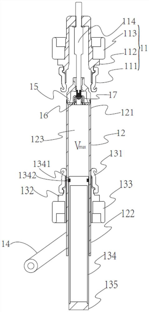
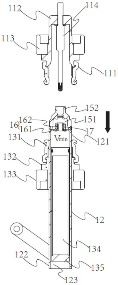
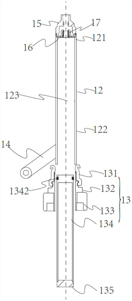
[0047] figure 1 It is a sectional view of the arc extinguishing load switch in the closing position according to the first embodiment of the present invention; figure 2 for figure 1 The sectional view of the arc extinguishing load switch in the shown embodiment in the opening position; image 3 for figure 1 A schematic structural diagram of a state in which the conductive rod of the switch in the illustrated embodiment is separated from the second conductive end.

[0048] like Figure 1-3 As shown, the arc extinguishing load switch includes a first conductive terminal 11 and a second conductive terminal 13 (see image 3 ) and a conductive rod 12 driven to move. Through the movement of the conductive rod 12, the first conductive end 11 and the second conductive end 13 can be electrically connected or disconnected, so as to realize the closing and opening operations of the switch.

[0049] in figure 1 An example is the closed state, the first end 121 of the conductive ro...

Embodiment 2

[0065] Figure 4 It is a schematic diagram of the enlarged structure of the switch air nozzle and the moving arc contact in the second preferred embodiment of the present invention; Figure 5A It is a schematic cross-sectional view of the moving arcing contact of the switch according to the second preferred embodiment of the present invention. Figure 5B It is a schematic plan view of the moving arcing contact of the switch according to the second preferred embodiment of the present invention.

[0066] Figure 4 , Figure 5A , Figure 5B Corresponding to the second embodiment of the present invention, in this embodiment, the optimization and improvement are mainly carried out on the air flow nozzle 15 and the moving arc contact 16 , and other parts refer to the description of the first embodiment, which will not be described again. The traditional airflow nozzle either has no cavity for accumulating airflow at all, or does not do any research and design on the flow field o...


PUM


Abstract

The invention relates to electric power equipment technology, and specifically discloses an arc-extinguishing load switch, which includes first and second conductive terminals and a conductive rod driven to reciprocate. The movement of the conductive rod realizes closing and opening. The second conductive end includes a piston and a second contact; the second contact is arranged outside the piston with a gap between them; the conductive rod is a hollow cavity, installed in the gap, and accommodates the piston in the cavity; The second contact and the conductive rod can maintain electrical connection during the movement; the cavity of the conductive rod and the piston form a volume-variable gas accommodation space; the first conductive end includes a first contact; the conductive rod end The part is provided with an air flow nozzle and a gas generating element communicating with the gas containing space. When the switch is opened, the conductive rod moves down to reduce the gas holding space to generate high-pressure airflow to extinguish the arc generated by the switch; at the same time, the gas-generating element at the end of the conductive rod releases the arc extinguishing gas under the action of the arc to extinguish the arc.

Description

technical field [0001] The invention relates to electric power equipment technology, in particular to an arc extinguishing load switch with two arc extinguishing modes of compressed gas arc extinguishing and gas generation arc extinguishing. Background technique [0002] When a switching device is used to disconnect the current, if the circuit voltage is higher than 10-20 volts and the current is higher than 80-100 mA, an arc will be generated between the contacts of the electrical device. Arc is a strong and long-lasting gas discharge phenomenon between the two poles. It is essentially a high-temperature and high-conductivity free gas. It not only has a great destructive effect on the contacts, but also prolongs the time for disconnecting the circuit. [0003] There are mainly five types of 12kV medium voltage load switchgear on the market: oil-immersed type, compressed air type, gas-generating type, SF6 (sulfur hexafluoride) gas type, and vacuum type. Although the vacuum ...

Claims


Application Information

Patent Timeline
Patent Type & Authority Patents(China)
IPC IPC(8): H01H33/70H01H33/91
Inventor 梁景璇游一民郑闽生林坚
Owner XIAMEN HUADIAN SWITCHGEAR
Why Eureka
Try Eureka