Ventilation and heat dissipation device of low-voltage complete device

A complete set of technology for ventilation and heat dissipation, low-voltage, applied in measurement devices, electrical devices, cooling/ventilation of substations/switch devices, etc., can solve the problem that the measurement accuracy of thermistors cannot be further improved, the heat of heating components cannot be discharged in time, Internal components, insulation parts aging damage and other problems, to achieve the effect of simple structure, easy maintenance, good dustproof function

Inactive Publication Date: 2018-01-09
陕西通时迪力信息技术有限公司
View PDF0 Cites 2 Cited by
  • Summary
  • Abstract
  • Description
  • Claims
  • Application Information

AI Technical Summary

Problems solved by technology

[0002] In the prior art, due to the intelligentization and intensification of low-voltage complete sets of equipment, a large number of heating components are installed in the cabinet, and the channels and spaces for heat dissipation are limited. The heat emitted by the heating components cannot be discharged in time when they are working, resulting in High temperature accelerates the aging and damage of components and insulation parts in the cabinet, and even causes electrical short circuit accidents in severe cases, spreading to the surrounding
[0003] Switching equipment, thus affecting the safe and stable operation of the power grid
In view of this, it is urgent to develop a low-pressure complete set of ventilation and heat dissipation device that overcomes the above-mentioned defects and discharge heat in time. This case arises from this, and heat dissipation devices generally need to use temperature sensors. In order to achieve rapid detection of temperature, traditional The method is to use heat-conducting materials to package the thermistor in the probe, but the measurement accuracy of the thermistor cannot be further improved

Method used


Image

  • Ventilation and heat dissipation device of low-voltage complete device
  • Ventilation and heat dissipation device of low-voltage complete device
  • Ventilation and heat dissipation device of low-voltage complete device

Examples


Embodiment Construction

[0013] The following will clearly and completely describe the technical solutions in the embodiments of the present invention with reference to the accompanying drawings in the embodiments of the present invention. Obviously, the described embodiments are only some, not all, embodiments of the present invention. Based on the embodiments of the present invention, all other embodiments obtained by persons of ordinary skill in the art without making creative efforts belong to the protection scope of the present invention.

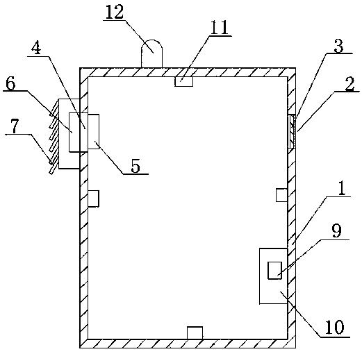
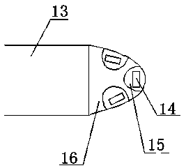
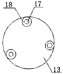
[0014] see Figure 1~3 , in an embodiment of the present invention, a low-voltage complete set of equipment ventilation and heat dissipation device includes an equipment casing 1, an air inlet 2 is provided on the right side of the equipment casing 1, and a dust-proof net 3 is arranged on the air inlet 2, The left side of the equipment housing 1 is provided with an air outlet 4, the inner side of the air outlet 4 is provided with a fan group 5, and the outer s...


PUM


Abstract

The invention discloses a ventilation and heat dissipation device for low-voltage complete equipment, which comprises an equipment casing, an air inlet is arranged on the right side of the equipment casing, an air outlet is arranged on the left side of the equipment casing, and a fan group is arranged on the inner side of the air outlet. The outer side of the air outlet is provided with a cooling grille, and the outer side of the cooling grille is equipped with a self-hanging louver air outlet. The inside of the equipment housing is equipped with an intelligent temperature controller, and the intelligent temperature controller is equipped with a wireless transmission module. There are also a number of temperature sensors, and an alarm device is provided on the upper end of the equipment shell. The temperature sensor includes a protective shell and a thermistor. There are several thermistors. The thermistor is located in the protective shell. A heat-conducting bonding material is provided, and a heat-insulating packaging material is provided on the outside of the heat-conducting bonding material, and a wire is connected to the thermistor, and a heat-conducting insulating material is provided on the outside of the wire. The invention has the advantages of simple structure, convenient use, good heat dissipation effect, high use safety and accurate temperature monitoring.

Description

technical field [0001] The invention relates to the technical field of electric power equipment, in particular to a ventilation and cooling device for low-voltage complete equipment. Background technique [0002] In the prior art, due to the intelligentization and intensification of low-voltage complete sets of equipment, a large number of heating components are installed in the cabinet, and the channels and spaces for heat dissipation are limited. The heat emitted by the heating components cannot be discharged in time when they are working, resulting in High temperature accelerates the aging and damage of components and insulation parts in the cabinet, and even causes electrical short circuit accidents in severe cases, spreading to the surrounding [0003] Switching equipment, thus affecting the safe and stable operation of the power grid. In view of this, it is urgent to develop a low-pressure complete set of ventilation and heat dissipation device that overcomes the abov...

Claims


Application Information

Patent Timeline
Patent Type & Authority Applications(China)
IPC IPC(8): H02B1/56G01K7/22
Inventor 刘丽
Owner 陕西通时迪力信息技术有限公司
Why Eureka
Try Eureka