Equivalent static simulation method of dynamic wireless power supply based on open-circuit voltage of receiving end

A technology of open circuit voltage and simulation method, applied in the direction of electrical components, circuit devices, etc., can solve problems such as laborious and time-consuming demonstration stages, and achieve the effect of improving research and development efficiency

Active Publication Date: 2018-01-09
HARBIN INST OF TECH
View PDF3 Cites 7 Cited by
  • Summary
  • Abstract
  • Description
  • Claims
  • Application Information

AI Technical Summary

Problems solved by technology

[0003] The purpose of the present invention is to solve the problem of time-consuming and labor-intensive problems in the scheme demonstration stage, which needs to build an actual dynamic driving platform to conduct experimental demonstration and working condition test of the dynamic wireless power supply system in the prior art. Static simulation method for dynamic wireless power supply with open-circuit voltage equivalent

Method used


Image

  • Equivalent static simulation method of dynamic wireless power supply based on open-circuit voltage of receiving end
  • Equivalent static simulation method of dynamic wireless power supply based on open-circuit voltage of receiving end
  • Equivalent static simulation method of dynamic wireless power supply based on open-circuit voltage of receiving end

Examples


specific Embodiment approach 1

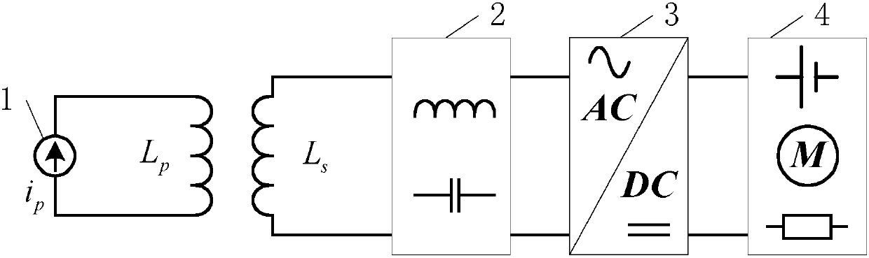
[0027] Specific implementation mode one: see figure 1 Describe this embodiment mode, a static simulation method of dynamic wireless power supply based on the equivalent open circuit voltage of the receiving end described in this embodiment mode, the static simulation method is realized based on a static wireless charging device, and the static wireless charging device includes a transmitter The end and the receiving end, the transmitting end and the receiving end are magnetically coupled, and the two are relatively static;

[0028] The transmitting end includes a controllable current excitation source 1 and a transmitting coil L p ;

[0029] The receiving end includes the receiving coil L s , No. 1 compensation network module 2 and vehicle-mounted regulation converter 3;

[0030] The controllable current excitation source 1 is used for transmitting coil L p Provides high-frequency alternating current i with varying amplitude p , the transmitting coil L p with receiving ...

specific Embodiment approach 2

[0043] Specific implementation mode two: see figure 1 and figure 2 This embodiment is described. The difference between this embodiment and the static simulation method for dynamic wireless power supply based on the equivalent open-circuit voltage of the receiving end described in the first embodiment is that the high-frequency alternating current i p The change law of is obtained by the simulation of the dynamic wireless charging device or the experiment of a magnetic coupler of one unit.

specific Embodiment approach 3

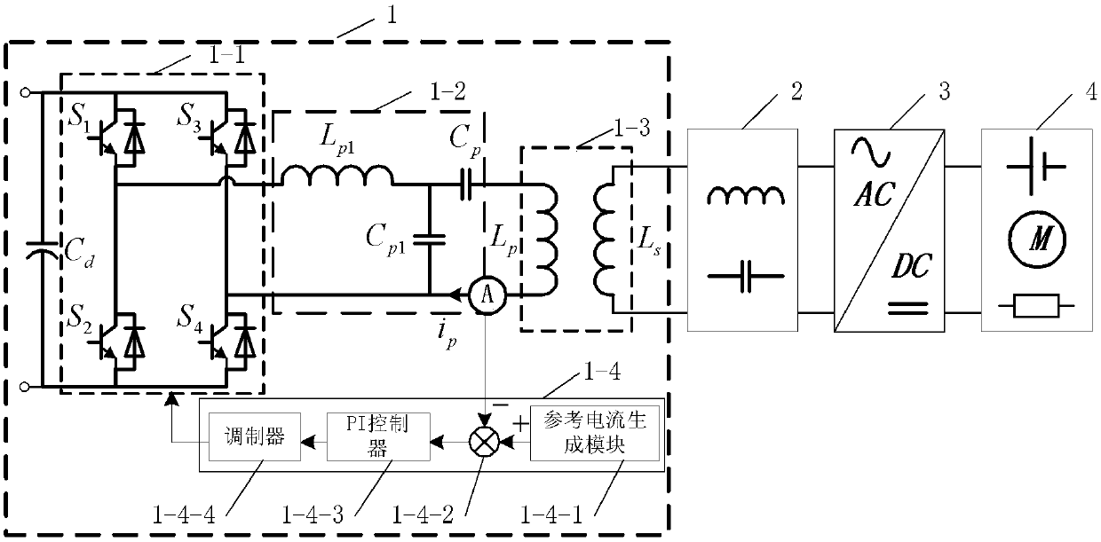
[0044] Specific implementation mode three: see figure 1 and figure 2 Describe this embodiment. The difference between this embodiment and the static simulation method for dynamic wireless power supply based on the equivalent open-circuit voltage of the receiving end described in the first embodiment is that the controllable current excitation source 1 includes a capacitor C d , H-bridge inverter 1-1, LCC compensation network 1-2, current sensor and main controller 1-4;

[0045] Capacitance C d The two ends of the H-bridge inverter 1-1 are connected to the DC voltage input terminal, the H-bridge inverter 1-1 is used to convert the received DC power into AC power, and the AC voltage output terminal of the H-bridge inverter 1-1 Connect with the voltage input terminal of the LCC compensation network 1-2, the voltage output terminal of the LCC compensation network 1-2 is connected with the transmitting coil L p The two ends of the connection;

[0046] Capacitance C d The two...


PUM


Abstract

The invention provides an equivalent static simulation method of dynamic wireless power supply based on an open-circuit voltage of a receiving end, belongs to the field of wireless electric energy transmission, and solves the problem that a scheme argumentation stage is time-consuming and labor-consuming since a practical dynamic driving platform needs to be established to conduct experiment argumentation and condition tests on a dynamic wireless power supply system in the prior art. According to the static simulation method, the reception of a coil open-circuit voltage by a dynamic wireless charging device is simulated through control of a current of a transmitting coil Lp of a static wireless charging device so that the dynamic-to-static simulation is realized. The method is mainly usedfor simulating dynamic wireless power supply.

Description

technical field [0001] The invention belongs to the field of wireless power transmission. Background technique [0002] Dynamic wireless charging technology can realize battery charging or direct drive power supply of electric vehicles during driving, which has a very positive effect on improving the cruising range and energy utilization efficiency of electric vehicles. In the early research and development of dynamic wireless power supply technology, R&D personnel need to build an experimental test platform that is close to the characteristics of actual vehicle driving conditions. In order to meet the test requirements of high-power and high-speed driving, the test platform has to invest a lot of money to build and meet the test requirements. The required sports car site and the laying of a considerable length of launch guide rail, but the direct construction of a dynamic wireless power supply test platform is quite time-consuming and expensive for the early stage of the pr...

Claims


Application Information

Patent Timeline
Patent Type & Authority Applications(China)
IPC IPC(8): H02J50/10
Inventor 张千帆宋双成董帅朱春波贾旭
Owner HARBIN INST OF TECH
Why Eureka
Try Eureka