Automatic smoke gas purifying device

An automatic purification and flue gas technology, applied in chemical instruments and methods, mixers, fluid mixers, etc., can solve problems such as low precision, poor purification effect, and uneven purification reaction.

Active Publication Date: 2018-01-12
池州市星聚信息技术服务有限公司
View PDF7 Cites 4 Cited by
  • Summary
  • Abstract
  • Description
  • Claims
  • Application Information

AI Technical Summary

Problems solved by technology

When the flue gas is directly introduced into the liquid medicine, it is difficult for the flue gas to fully mix with the solution at the place where the flue gas gathers, resulting in poor purification effect, and to atomize the liquid medicine and mix the flue gas requires a large number of atomizing nozzles and pressurized system, leading to high cost of purification equipment, and when replenishing the liquid medicine, the liquid medicine is often pumped directly into the high-pressure water pipe, and the mixing of water and liquid medicine is completed during the transmission process. Since the liquid medicine is directly pumped into the high-pressure water pipe, local The concentration is not uniform, which leads to uneven purification reaction and affects the effect of flue gas purification. At the same time, the existing liquid medicine delivery mechanism can only carry out quantitative delivery or low-precision medicine liquid delivery, and it is difficult to adjust the amount of medicine delivered and the Quantity precise control

Method used


Image

  • Automatic smoke gas purifying device
  • Automatic smoke gas purifying device
  • Automatic smoke gas purifying device

Examples


Embodiment Construction

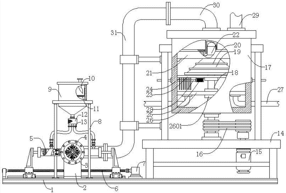
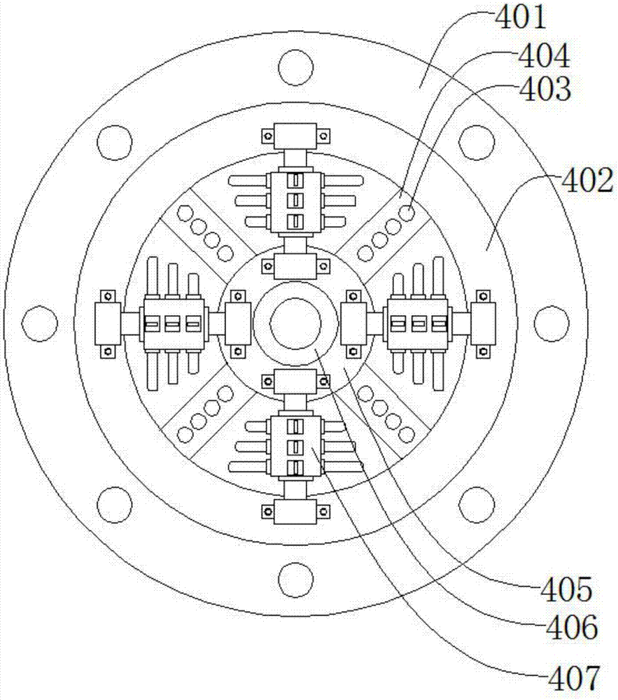
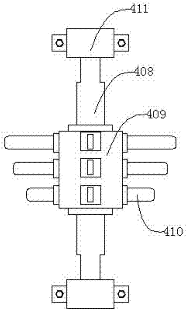
[0055] Such as figure 1 , figure 2 , image 3 , Figure 4 , Figure 5 , Figure 6 , Figure 7 , Figure 8As shown, an automatic flue gas purification device includes a base 1, a bracket 2, a water inlet pipe 3, a dispensing mechanism 4, a pumping mechanism 5 symmetrically arranged in two pieces along the dispensing mechanism 4, a lead screw 6, a servo Motor 7, first support 8, medicine tank 9, liquid medicine inlet pipe 10, filter screen 11, shunt box 12, shunt pipe 13, the second support 14, speed regulation Motor 15, transmission mechanism 16, purification tank 17, first rotating shaft 18, conical head 19, spinner 20 whose diameters are uniformly distributed from top to bottom along the conical head 19 and whose number is no less than 2 pieces, and which are equipped with Air plate 21, deflector head 22, upper partition 23, intubation pipe 24, gas collection box 25, lower partition 26, sewage pipe 27, clean gas outlet pipe 28, flue gas inlet pipe 29, liquid inlet pip...


PUM


Abstract

The invention discloses an automatic smoke gas purifying device. The automatic smoke gas purifying device comprises a base, a bracket, a water inlet tube, a medicine distributing mechanism, two medicine pumping mechanisms which are symmetrically arranged along the medicine distributing mechanism, a lead screw, a servo motor, a first bracket, a medicine tank, a medicine liquor inlet tube, a filterscreen, a distributing box, at least two distributing tubes which are symmetrically arranged along the distributing box, a second bracket, a speed-regulating motor, a transmission mechanism, a purifying tank, a first rotary shaft, a tapered head, not less than two throwing discs which are uniformly distributed along the tapered head from top to bottom, and are gradually increased in diameter, an air distributing plate, a guide head, an upper partition, an insertion tube, a gas collecting box, a lower partition, a sewage tube, a purified gas outlet tube, a smoke gas inlet tube, a liquid inlet tube, and a connecting hose. The device is simple in structure, performs primary reaction on the smoke gas and atomized medicine liquor, and performs secondary reaction on the smoke gas and the atomized medicine liquor, so that the smoke gas is automatically purified; and moreover, medicine pumping amount is precise and adjustable, reaction medicine liquor is automatically proportioned and pumped,the medicine liquor is uniformly and continuously mixed with water, the smoke gas purifying efficiency is high, and the smoke gas purifying effect is good.

Description

technical field [0001] The invention relates to a mechanical device, in particular to an automatic flue gas purification device. Background technique [0002] With the development of industry and the improvement of people's living standards, the thirst for energy is also increasing. SO2 in coal-fired flue gas has become the main cause of air pollution. Reducing SO2 pollution has become the top priority of today's atmospheric environment governance. Many smokers The gas desulfurization process has been widely used in industry. Among them, the wet desulfurization technology is widely used because of its mature technology and simple process. The process of wet desulfurization is generally as follows: the flue gas is dedusted and then neutralized with the chemical solution In the reaction process, the liquid medicine is supplemented according to the pH value until the desulfurization is completed. There are two methods for mixing the flue gas and the liquid medicine. One is to d...

Claims


Application Information

Patent Timeline
Patent Type & Authority Applications(China)
IPC IPC(8): B01D53/78B01D53/50B01F5/20B01F5/00
CPCY02A50/20
Inventor 施明
Owner 池州市星聚信息技术服务有限公司
Why Eureka
Try Eureka