
Flying shear controlling system and method

A flying shear control and control unit technology, applied in the field of flying shear control system, can solve the problems of poor control performance, slow operation speed and high overall cost, and achieve the effect of improving performance and smooth motion

Pending Publication Date: 2018-01-12
YANGCHUN NEW STEEL CO LTD
View PDF0 Cites 7 Cited by
  • Summary
  • Abstract
  • Description
  • Claims
  • Application Information

AI Technical Summary

Problems solved by technology

The flying shear control system of the rod and wire production line of metallurgical enterprises adopts AC or DC speed regulation system. The flying shear control system in the prior art generally uses the PLC control system or the process controller (such as T400, FM458) as the control core. They have some Disadvantages: 1. The T400 module has been discontinued, and subsequent spare parts cannot be guaranteed, and the T400 can only be used for the older generation of Siemens AC / DC speed control products
2. The FM458 module itself is expensive and needs to be used with S7-400PLC. The overall cost is relatively high
3. Ordinary PLC has slow operation speed and poor control performance, while the price of motion control PLC is higher

Method used


Image

  • Flying shear controlling system and method
  • Flying shear controlling system and method
  • Flying shear controlling system and method

Examples


Embodiment

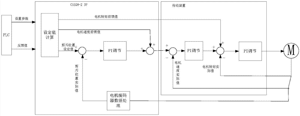
[0048] This embodiment discloses a flying shear control system, such as figure 1 As shown, including PLC and CU320-2DP control unit as the position closed-loop control unit;

[0049] In this embodiment, the PLC is connected to the CU320-2DP control unit to generate the target position value of the cutting blade, the maximum speed value of the cutting blade and the maximum acceleration value of the cutting blade, and send them to the CU320-2DP control unit. In this embodiment, the PLC can Send the above data to the CU320-2DP control unit through the Profibus-DP bus; the PLC provides a man-machine interface for the operator to set parameters. In this embodiment, the operator can set the relevant parameters such as the cutting length in the PLC through the man-machine interface The PLC in the flying shear control system of the present embodiment is connected to the rolling line control system, obtains the speed value of the upstream rolling mill and the speed value of the downstr...


PUM


Abstract

The invention discloses a flying shear controlling system and method. The flying shear controlling system comprises a PLC and a CU320-2DP controlling unit which serves as a position closed loop controlling unit; the PLC is connected with the CU320-2DP controlling unit; the CU320-2DP controlling unit is connected with a transmission device, and the PLC generates a shear blade target position value,a shear blade maximum speed value and a shear blade maximum acceleration value; the CU320-2DP controlling unit calculates a shear blade position setting value, a motor speed setting value and a motortorque feedforward value and conducts position closed-loop controlling according to the shear blade position setting value and a shear blade position actual value, and the motor speed setting value is obtained by adding a motor speed compensation value and a motor speed feedforward value and is sent to the transmission device for speed closed-loop controlling; and the motor torque feedforward value is sent to the transmission device for torque closed-loop controlling. According to the flying shear controlling system and method, the CU320-2DP controlling unit is used as a controlling core, andthe flying shear controlling system and method have the beneficial effects of being low in cost, wide in applicability and high in performance.

Description

technical field [0001] The invention belongs to the control technology of start-stop flying shear equipment for a bar and wire production line of a metallurgical enterprise, and in particular relates to a flying shear control system and method. Background technique [0002] Flying shear is the key equipment in the rod and wire production line of metallurgical enterprises. It is installed on the continuous rolling line and can cut the rolling stock horizontally. The flying shear control system of the rod and wire production line of metallurgical enterprises adopts AC or DC speed regulation system. The flying shear control system in the prior art generally uses the PLC control system or the process controller (such as T400, FM458) as the control core. They have some Disadvantages: 1. The T400 module has been discontinued, and the follow-up spare parts cannot be guaranteed, and the T400 can only be used for the older generation of Siemens AC / DC speed control products. 2. The F...

Claims


Application Information

Patent Timeline
IPC IPC(8): B23D25/02B23D36/00B21B15/00B21B37/00
Inventor 刘晓明袁春伟
Owner YANGCHUN NEW STEEL CO LTD
Learn More