
Automatic welding equipment applied to furniture production line

An automatic welding and production line technology, applied in the direction of welding equipment, auxiliary welding equipment, welding/cutting auxiliary equipment, etc., can solve the problems of not having a good buffer for vibration, reducing the service life of the equipment, and affecting the performance of the equipment, so as to achieve good reduction Shock effect, protection equipment, work stability effect

Inactive Publication Date: 2018-01-12
惠州市百意居实业有限公司
View PDF0 Cites 3 Cited by
  • Summary
  • Abstract
  • Description
  • Claims
  • Application Information

AI Technical Summary

Problems solved by technology

[0002] Automatic welding machine is an automatic welding equipment used in furniture production line based on motor control technology, single chip microcomputer control technology, PLC control technology and numerical control technology. Automatic welding equipment is bulky and inconvenient to move. Some equipment with pulleys have poor stability when they are not moving. When the light is poor, there is no good light source for welding, which is inconvenient to use. When the equipment is working, it is easy to Generates a lot of heat, if it is not dissipated in time, it will affect the performance of the equipment, and the vibration generated when the equipment is moved or transported is not well cushioned and lowered, which will reduce the service life of the equipment

Method used


Image

  • Automatic welding equipment applied to furniture production line
  • Automatic welding equipment applied to furniture production line
  • Automatic welding equipment applied to furniture production line

Examples


Embodiment Construction

[0021] The preferred embodiments of the present invention will be described below in conjunction with the accompanying drawings. It should be understood that the preferred embodiments described here are only used to illustrate and explain the present invention, and are not intended to limit the present invention.

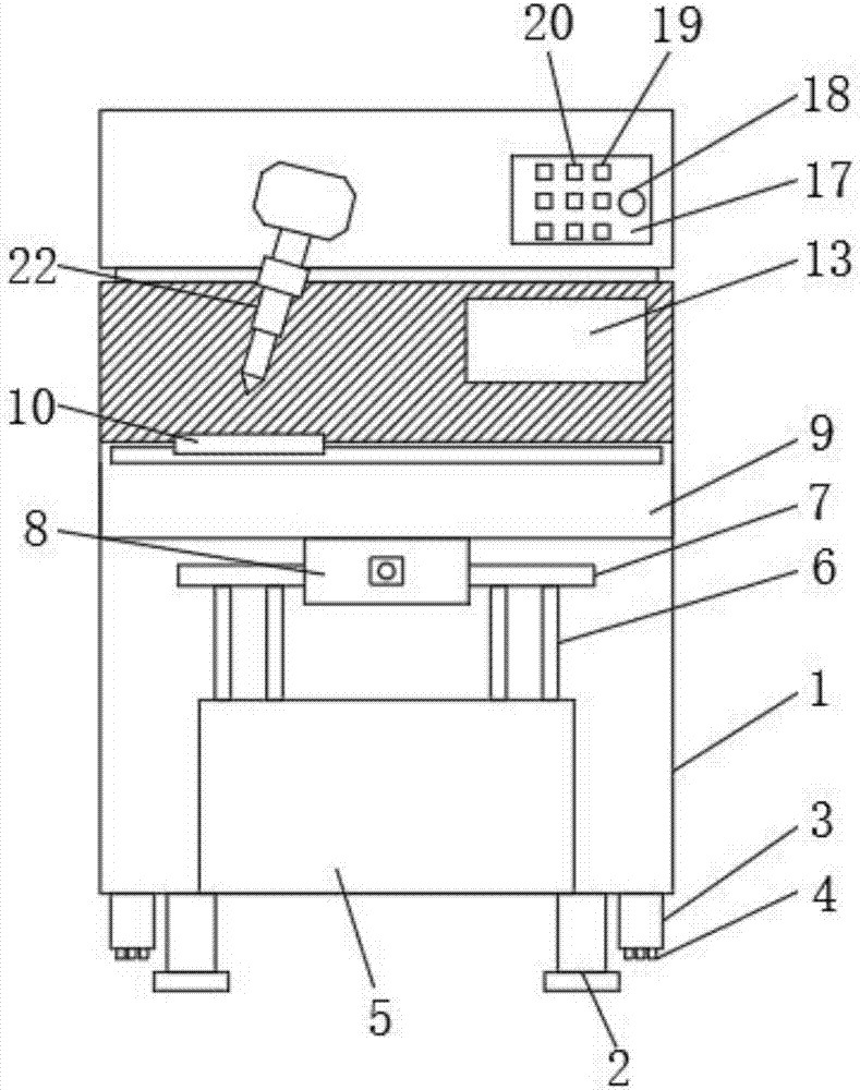
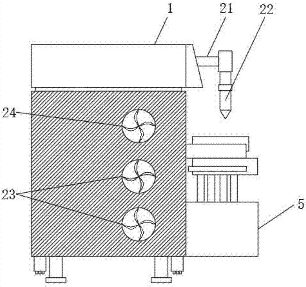
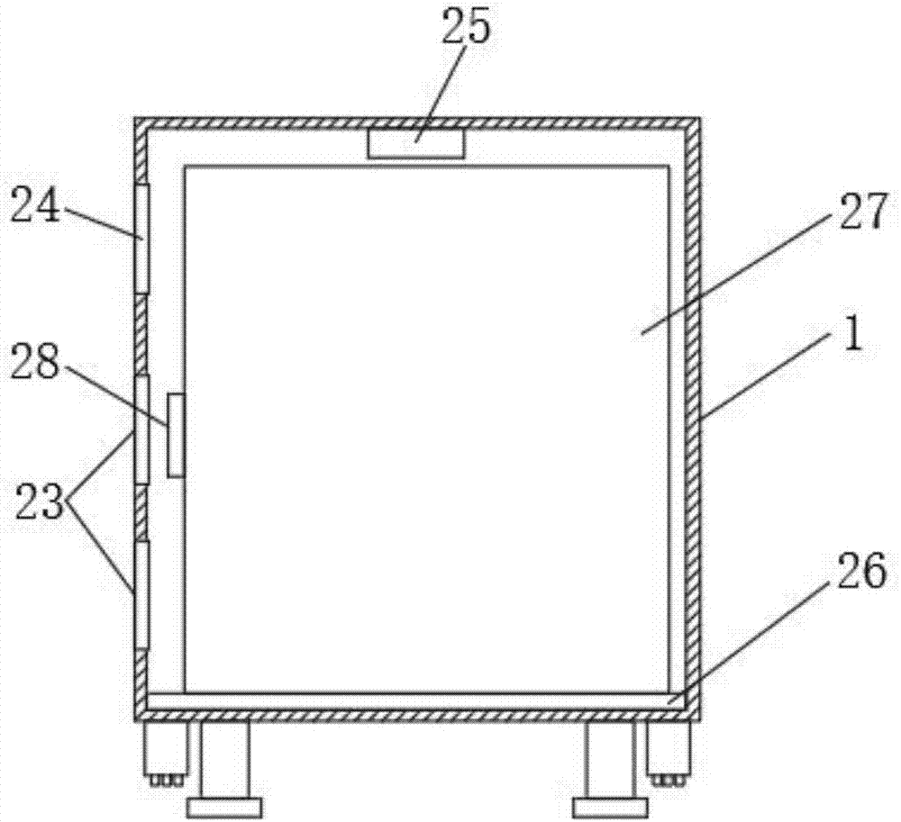
[0022] see Figure 1-5 , the present invention provides a technical solution: an automatic welding equipment applied to a furniture production line, including a chassis 1, a leg 2, an electro-hydraulic rod 3, a pulley 4, a hydraulic box 5, a hydraulic column 6, a connecting plate 7, a fastening Block 8, vertical moving platform 9, horizontal moving workbench 10, groove 11, hinge 12, groove cover 13, universal pipe 14, lighting 15, battery 16, control panel 17, power switch 18, electric hydraulic lever switch 19. Light switch 20, rotating shaft 21, welding head 22, first cooling fan 23, second cooling fan 24, temperature sensor 25, shock absorber 26, welding applianc...


PUM


Abstract

The invention discloses automatic welding equipment applied to a furniture production line. The automatic welding equipment applied to the furniture production line comprises a machine box, electric hydraulic rods, sliding wheels, an illumination lamp and a shock absorber. Each electric hydraulic rod is mounted on the outer side of a supporting leg. The sliding wheels are mounted at one end of each electric hydraulic rod. A universal joint pipe is mounted in a groove. The illumination lamp is mounted at one end of the universal joint pipe. A storage battery is mounted on one side of the illumination lamp. First heat dissipation fans are mounted at the bottoms of the two sides of the machine box. A second heat dissipation fan is mounted above the first heat dissipation fans. A temperature sensor is mounted at the top end in the machine box. The shock absorber is mounted at the bottom end in the machine box. An electric welding device is mounted at the top end of the shock absorber. Damping springs are uniformly mounted in the shock absorber. The automatic welding equipment is suitable for the furniture production line, furniture accessories are welded automatically, the movement isconvenient, and the working stability is high; the illumination device is arranged, the heat dissipation efficiency is high, and intelligent control is achieved; and meanwhile, the good shock absorption effect is achieved, the use is convenient, and the service life of the equipment is prolonged.

Description

technical field [0001] The invention relates to a welding machine, in particular to an automatic welding equipment applied to a furniture production line. Background technique [0002] Automatic welding machine is an automatic welding equipment used in furniture production line based on motor control technology, single chip microcomputer control technology, PLC control technology and numerical control technology. Automatic welding equipment is bulky and inconvenient to move. Some equipment with pulleys have poor stability when they are not moving. When the light is poor, there is no good light source for welding, which is inconvenient to use. When the equipment is working, it is easy to A lot of heat is generated, if it is not dissipated in time, it will affect the performance of the equipment, and the vibration generated when the equipment is moved or transported is not well cushioned and lowered, which will reduce the service life of the equipment. [0003] Therefore, how...

Claims


Application Information

Patent Timeline
Patent Type & Authority Applications(China)
IPC IPC(8): B23K37/00
Inventor 梁仁霖
Owner 惠州市百意居实业有限公司
Learn More