Room-pillar-like type coal mining method for filling near goafs through roof cutting

A coal mining method and room-and-pillar technology, applied in the direction of filling, ground mining, mining equipment, etc., can solve problems such as unbalanced coal mining capacity and filling capacity, environmental loss, and difficulty in filling, and achieve effective control of surface subsidence , The effect of reducing the settlement is obvious, and the effect of reducing the filling cost

Inactive Publication Date: 2018-01-12
SHANDONG UNIV OF SCI & TECH
5 Cites 0 Cited by

AI-Extracted Technical Summary

Problems solved by technology

[0003] Unbalanced coal mining capacity and filling capacity: With the mechanization of fully mechanized mining and fully mechanized caving, the coal mining capacity has increased dramatically, but the filling capacity is limited by the slow solidification of filling materials and it is difficult to achieve breakthrough growth
[0004] Unbalanced supply and demand of filling materia...

Method used

The 4th step, as shown in Figure 5, charge sealing, according to " blasting engineering " book about deep-hole blasting introduction and field practice experience, blast hole 5 charge coefficients generally get 0.7, blasthole mud 3 coefficients Generally take 0.3...

Abstract

The invention discloses a room-pillar-like type coal mining method for filling near goafs through roof cutting. The direct roof initial caving pace L0 is obtained, and when footage of the coal miningprogress reaches one third of the initial caving pace L0, roof cutting is started from the position located behind a coal cutter by the distance of one basic unit; corresponding shot holes are formedin the roof cutting part of the corresponding basic unit, when the footage of the coal mining progress reaches two thirds of the initial caving pace L0, the roof cutting parts on the left side of thebasic unit are cut, and gangue produced at the three roof cutting parts are transferred to filling areas of the basic unit by mechanical equipment for filling; and the steps are repeatedly operated until coal mining of the coal mining area is completed. According to the room-pillar-like type coal mining method for filling the near goafs through roof cutting, the effect similar to that of room-pillar type coal mining is achieved finally, surface subsidence can be effectively controlled, and the sedimentation reduction effect is obvious; no external filling materials are required, only the costof the mechanical equipment is input at a time, and filling cost is reduced; and the room-pillar-like type coal mining method is not limited by slow solidification of paste materials, the supporting effect is achieved once filling is completed, and filling efficiency is high.

Application Domain

Underground miningSurface mining +1

Technology Topic

Filling materialsCoal mining +4

Image

  • Room-pillar-like type coal mining method for filling near goafs through roof cutting
  • Room-pillar-like type coal mining method for filling near goafs through roof cutting
  • Room-pillar-like type coal mining method for filling near goafs through roof cutting

Examples

  • Experimental program(1)

Example Embodiment

[0037] The present invention provides a room-and-pillar-like coal mining method of roof cutting and filling adjacent goaf. It should be understood that the specific embodiments described herein are only used to explain the present invention, but not to limit the present invention.
[0038] The invention provides a room-and-pillar-like coal mining method for roof cutting and filling adjacent goaf, which comprises the following steps:
[0039] Step 1. Obtain the first caving step distance L of the direct top 0 , and divide the coal mining area into several basic units. The size of the basic unit is the initial caving step distance multiplied by 4 times the width of the roof cutting roof, of which the width of the roof cutting roof is 8m; when the footage of the coal mining progress reaches the initial Falling step distance L 0 When 1/3 of , start cutting the top from the distance of one basic unit behind the shearer;
[0040] Step 2. Arrange corresponding blastholes on the cut top of the corresponding basic unit, the thickness of the cut top is the coal mining thickness, and the plane size at the cut top is 1/3L 0 A square multiplied by 8, two groups of blastholes are arranged at the top cut, each group of blastholes is arranged with 5 blastholes, the depth of each blasthole is twice the thickness of the coal, the diameter of the blasthole is greater than 80 mm, and the top cut remains intact;
[0041] Step 3. The footage of the coal mining progress reaches 2/3L 0 When , the cut tops on the left side of the basic unit are all cut off, and the gangue generated at the three cut tops is moved to the filling area of ​​the basic unit by mechanical equipment for filling;
[0042] Step 4. The footage of the coal mining progress reaches L 0 When the two roof cutting units above the basic unit are cut off, a mechanized equipment is used to move the left roof and the two roofs cut above to the filling area of ​​the basic unit. At this point, the coal mining of a basic unit , top cutting and filling are completed; this cycle operation until the coal mining area is completed, the recovery rate reaches 100%, and the filling rate reaches 50%;
[0043] Wherein, the above-mentioned roof cutting refers to cutting off the corresponding direct roof and dropping gangue to fill the filling area of ​​the basic unit.
[0044] In another preferred embodiment of the present invention, the above-mentioned step 1 specifically further includes: arranging the working face according to the long-wall mining, in order to keep the roof from slumping during the direct roof mining process, it is necessary to make the mining width L of the small strip of coal smaller than the direct mining width L The first caving step of the top L 0 , in the initial mining, the direct top rock stratum can be regarded as a double-ended fixed beam supported by coal walls and coal pillars at both ends. The span of the double-ended fixed beam increases with the advancement of the working face. When the limit value is reached, Due to the action of its own self-weight load, it will break, lose balance, and form caving, directly topping the initial caving step distance L 0 for:
[0045]
[0046] where: m z - thickness of direct top, m;
[0047] σ t is the tensile strength of the direct top rock layer;
[0048] q is the uniformly distributed load density shown by the direct top rock beam.
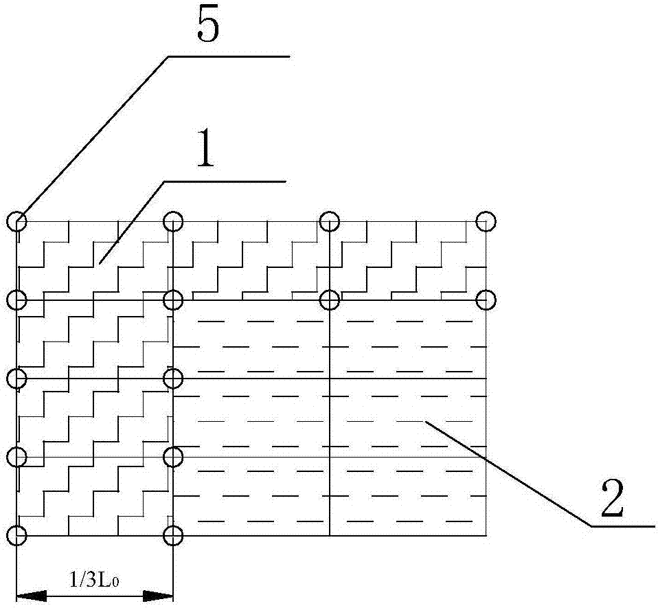
[0049] and as figure 1 As shown, the above-mentioned basic unit is composed of 3×4 small units, of which there are six cut tops 1 and six filling areas 2, and the cut tops are located right in front of the filling area.
[0050] Further, the above-mentioned step 2 specifically also includes:
[0051] The charge coefficient of the upper blasthole is 0.7, the mud coefficient is 0.3, and the continuous coupling method is adopted. Blasting to cut the top, use double detonators, double detonators to detonate, two detonating cords extend to the bottom of the blasthole, each detonating cord uses a detonator, and the two detonators are connected in parallel. The detonating cord should be tied firmly, and the energy-forming hole end of the detonator should be in the same direction as the detonating cord.
[0052] In order to describe the present invention in more detail, more detailed embodiments are listed below for description.
[0053] The first step is to arrange the working face according to the longwall mining. In order to keep the roof from caving during the direct roof mining process, it is necessary to make the coal mining width L of the small strip smaller than the initial caving step distance L of the direct roof. 0 , in the initial mining, the direct top rock formation can be regarded as a double-ended fixed beam supported by the coal wall and the coal pillar at both ends, and the span of the beam increases with the advancement of the working face. The action of self-weight load will break, lose balance and form caving. Therefore, the first caving step L of the direct top can be derived 0 :
[0054]
[0055] In the formula: m z - thickness of direct top, m;
[0056] σ t - the tensile strength of the direct top rock layer (body);
[0057] q—the uniformly distributed load density shown by the direct top rock beam.
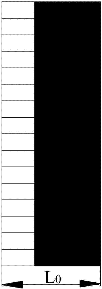
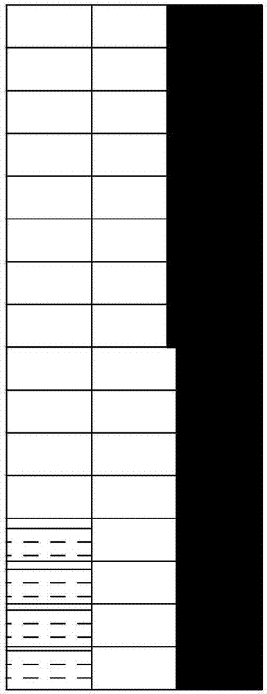
[0058] The second step, such as figure 1 As shown, the basic unit is designed. The above basic unit is composed of 3×4 small units, of which there are six cut tops 1 and six filling areas 2. The cut top is located directly in front of the filling area, and the size of the basic unit is the initial caving step. The distance is multiplied by 4 times the width of the roof for cutting the roof, and the width of the roof for cutting the roof is about 8m; such as figure 2 , image 3 shown, when the footage reaches the initial caving step 1/3L 0 At the same time, due to the long time for roof cutting and moving, the coal mining team enters the maintenance state.
[0059] The third step, such as figure 1 , image 3 and Figure 4 As shown, four topping units on the left side of the first basic unit are topped, as shown in figure 1 and Figure 4 As shown, the thickness of the top cut is close to the thickness of the coal, and the plane size is 1/3L 0 Multiply by 8m, 5 blastholes 5 groups, a total of two groups; the depth of each blasthole 5 is double the mining thickness, the diameter of the blasthole 5 is greater than 80mm, and the top cut remains intact.
[0060] The fourth step, such as Figure 5 According to the introduction of deep hole blasting in the book "Blasting Engineering" and on-site practical experience, the charge coefficient of blasthole 5 is generally taken as 0.7, and the coefficient of taphole 3 is generally taken as 0.3, such as Figure 10 As shown in the figure, water cannon mud 3 is used to reduce dust, cool down and absorb poisonous and harmful gases. The blasthole 5 adopts a simplified interval charging method, that is, a continuous coupling method is used for charging.
[0061] The fifth step, such as Image 6 As shown, the blasting is cut to the top, and the double detonators 4 are used to detonate the double detonation. Two detonating cords 6 extend to the bottom of the blasthole. Each detonating cord adopts a detonator 4, and the two detonators are connected in parallel. Bind the detonator 4 and the detonating cord 6 firmly with tape paper. Note that the energy-gathering hole end of the detonator should be in the same direction as the detonating cord's transmission direction;
[0062] The sixth step, such as Figure 7 As shown, the footage reaches 2/3L 0 , the top-cutting units on the left side of the basic unit are all cut off, and the gangue generated at the three top-cutting places is moved to the filling area of ​​the basic unit by mechanical equipment for filling;
[0063] The seventh step, such as Figure 8 and Figure 9 shown, the footage reaches L 0 At this time, the two top-cutting units above the basic unit are cut off, and mechanized equipment is used to move the left-side roof and the two top-cut tops to the filling unit. The filling is completed, the recovery rate reaches 100%, and the filling rate reaches 50%. The filling effect is as follows: Figure 10 , 11 shown.
[0064] Of course, the above descriptions are only the preferred embodiments of the present invention, and the present invention is not limited to the above-mentioned embodiments. , and obvious deformation forms, all fall within the essential scope of this specification, and should be protected by the present invention.

PUM

no PUM

Description & Claims & Application Information

We can also present the details of the Description, Claims and Application information to help users get a comprehensive understanding of the technical details of the patent, such as background art, summary of invention, brief description of drawings, description of embodiments, and other original content. On the other hand, users can also determine the specific scope of protection of the technology through the list of claims; as well as understand the changes in the life cycle of the technology with the presentation of the patent timeline. Login to view more.

Similar technology patents

Method for calculating actual mining thickness of underground coal gasification

ActiveCN112881170AReduce redundant wasteImprove recovery
Owner:CHINA UNIV OF MINING & TECH

Environment-friendly high-elasticity antistatic fabric and production technology thereof

InactiveCN113122992Aincrease elasticityImprove recovery
Owner:宁波吾焱服饰科技有限公司

Method of producing an aromatised aqueous liquid

InactiveUS20140120227A1improve recoveryincrease in temperature
Owner:NESTEC SA

Autonomous subsea tieback enabling platform

PendingUS20220065064A1improve recoveryboost flow
Owner:KELLOGG BROWN & ROOT LLC

System and method for optimized production of hydrocarbons from shale oil reservoirs via cyclic injection

PendingUS20210340428A1improve recoverylower interfacial tension
Owner:SHALE INGENUITY LLC

Classification and recommendation of technical efficacy words

  • Improve recovery

Joint / tissue inflammation therapy and monitoring device

InactiveUS20050177093A1enhance recovery processimprove recovery
Owner:AMERICAN ENVIRONMENTAL SYST

Embedded dynamic alarm control system

InactiveUS20100241247A1improve recoveryreduce number
Owner:ATTARWALA FAKHRUDDIN T

Auto-prioritizing service impacted optical fibers in massive collapsed rings network outages

InactiveUS20090226162A1improve recoveryreduce damage
Owner:AMERICAN TELEPHONE & TELEGRAPH CO

Dielectric Ceramic Composition

InactiveUS20090105063A1suppress precipitationimprove recovery
Owner:YOKOWO CO LTD
Why Eureka
Try Eureka