Return water cooling system and control method of return water cooling system

A cooling system and return water technology, which is applied in household refrigeration equipment, lighting and heating equipment, household appliances, etc., can solve the problems of large floor area, high investment in heat exchangers, high cost of regular maintenance and cleaning of heat exchangers, and achieve The effects of stable water temperature, simple and convenient operation, reduction of workshop construction costs and initial equipment investment costs

Active Publication Date: 2018-01-12
KUNSHAN FLOWTECH ELECTROMECHANICAL ENG CO LTD
View PDF4 Cites 3 Cited by
  • Summary
  • Abstract
  • Description
  • Claims
  • Application Information

AI Technical Summary

Problems solved by technology

[0005] One of the objectives of the present invention is to propose a return water cooling system to solve the problems of high initial investment of heat exchangers, large footprint and high cost of regular maintenance and cleaning of heat exchangers

Method used


Image

  • Return water cooling system and control method of return water cooling system
  • Return water cooling system and control method of return water cooling system

Examples


Embodiment Construction

[0035] The technical solutions of the present invention will be further described below in conjunction with the accompanying drawings and through specific embodiments.

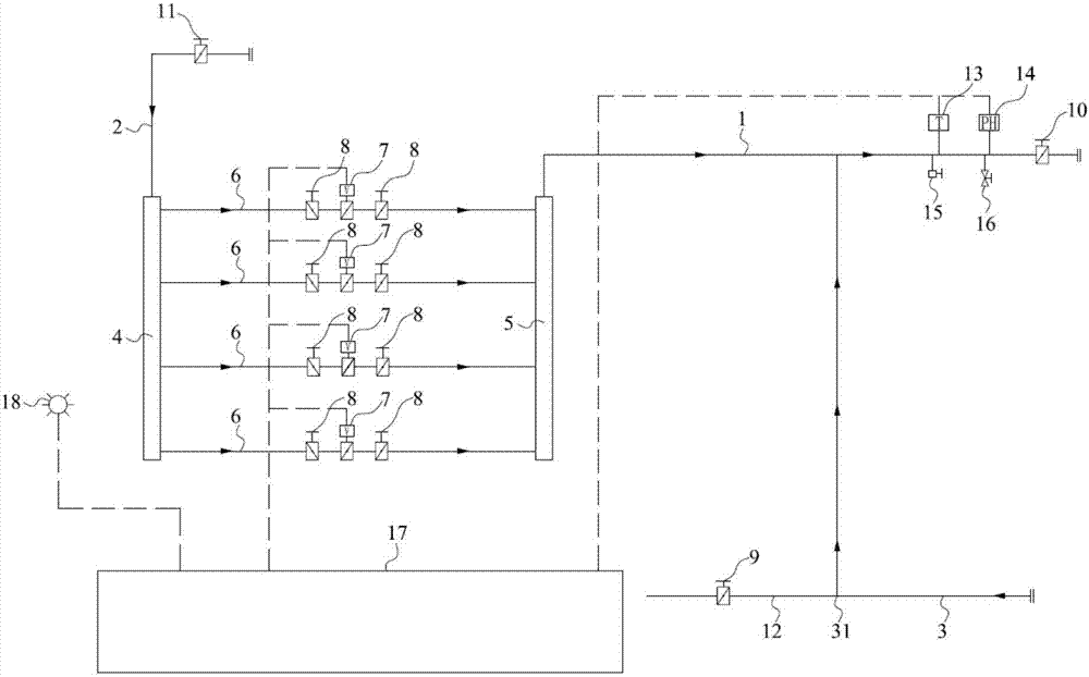
[0036] Such as figure 1 As shown, this embodiment discloses a return water cooling system, comprising: a main cold water supply pipe 2, a water separator 4, a cold water supply pipe, a water collector 5, and a cooling water supply pipe 1 that are fluidly connected in sequence, and the cooling water supply pipe 1 The pipe 1 is connected to the water inlet of the equipment to be cooled, the water outlet of the equipment is connected to the return water pipe 3, the return water pipe 3 is connected to the cooling water supply pipe 1, and the return water pipe 3 is provided with a process equipment water outlet 31. The water outlet 31 of the process equipment is connected with the water outlet pipe 12 of the process equipment, and part of the return water in the return water pipe 3 flows into the water outlet pipe ...


PUM


Abstract

The invention relates to the technical field of cooling and discloses a return water cooling system and a control method of the return water cooling system. The return water cooling system comprises acold water supply pipe, a cooling water supply pipe and a return water pipe. The cold water supply pipe comprises multiple water supply branch pipes. A control valve is mounted on each water supply branch pipe. The control valves are electrically connected with a PLC. One end of the cooling water supply pipe is connected with water outlet ends of the water supply branch pipes, and the other end of the cooling water supply pipe is connected with a water inlet of to-be-cooled equipment. The cooling water supply pipe is provided with a temperature sensor electrically connected with the PLC. Oneend of the return water pipe is connected with a water outlet of the equipment, and the other end of the return water pipe is connected with the cooling water supply pipe, and a water outlet is formedin the return water pipe. According to the return water cooling system, the opening of the control valves is controlled by the PLC so that return water of different flows can be mixed and cooled, theoperation is easy and convenient, no heat exchanger is needed, the equipment mounting space is reduced, the workshop building cost and the initial equipment investment cost are lowered, and the costin regularly maintaining and cleaning heat exchange boards is omitted.

Description

technical field [0001] The invention relates to the technical field of cooling, in particular to a return water cooling system and a control method thereof. Background technique [0002] The cooling circulation system of the workshop equipment usually uses a heat exchanger to communicate with the equipment to be cooled in fluid to form a cooling circulation system. Specifically, the cooling water pipe is connected to the water inlet of the equipment to be cooled to provide cooling water for the equipment to be cooled, and the water outlet of the equipment is connected to the return water pipe to discharge the return water after cooling the equipment to the heat exchanger for cooling , the water cooled by the heat exchanger is reused to cool the equipment. [0003] The above-mentioned cooling circulation system needs to be equipped with a heat exchanger, and the initial investment of assembling the heat exchanger and the water pump is high, and the floor area is large; and t...

Claims


Application Information

Patent Timeline
Patent Type & Authority Applications(China)
IPC IPC(8): F25D1/00F25D29/00
Inventor 许翔
Owner KUNSHAN FLOWTECH ELECTROMECHANICAL ENG CO LTD
Why Eureka
Try Eureka