
Display panel and display device

A technology for display panels and display areas, applied in semiconductor devices, electrical components, circuits, etc., and can solve problems such as uneven brightness

Active Publication Date: 2020-07-07
SHANGHAI TIANMA MICRO ELECTRONICS CO LTD
View PDF7 Cites 0 Cited by
  • Summary
  • Abstract
  • Description
  • Claims
  • Application Information

AI Technical Summary

Problems solved by technology

[0004] In view of this, an embodiment of the present invention provides a display panel and a display device, which are used to reduce the resistance of the cathode on the basis of ensuring the pixel aperture ratio, thereby solving the problem of uneven brightness existing in the existing organic light-emitting display devices

Method used


Image

  • Display panel and display device
  • Display panel and display device
  • Display panel and display device

Examples


Embodiment Construction

[0026] In order to make the purpose, technical solutions and advantages of the present invention clearer, the present invention will be further described in detail below in conjunction with the accompanying drawings. Obviously, the described embodiments are only some of the embodiments of the present invention, rather than all of them. Based on the embodiments of the present invention, all other embodiments obtained by persons of ordinary skill in the art without making creative efforts belong to the protection scope of the present invention.

[0027] The shapes and sizes of the components in the drawings do not reflect the real scale, but are only intended to schematically illustrate the content of the present invention.

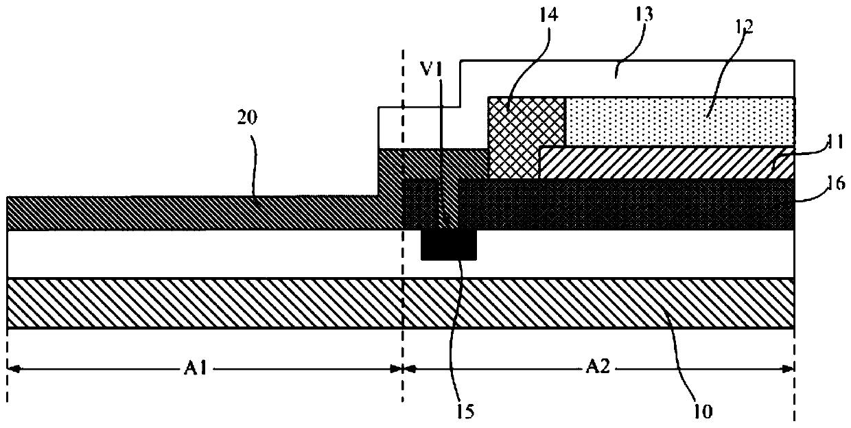
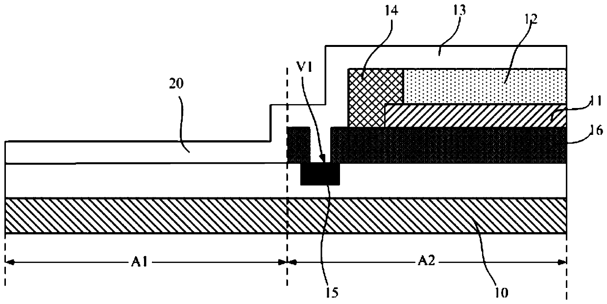
[0028] A display panel provided by an embodiment of the present invention, such as figure 2 as shown, figure 2 A schematic cross-sectional structure diagram of a display panel provided by an embodiment of the present invention; including an array substra...


PUM


Abstract

The invention discloses a display panel and a display device, which have a see-through area and a pixel display area. Since at least part of the see-through area has a transparent auxiliary electrode, and the transparent auxiliary electrode is electrically connected to the cathode in the adjacent pixel display area, and the transparent auxiliary The electrodes extend above the cathode auxiliary wiring and are electrically connected to the cathode auxiliary wiring, that is, the cathode is electrically connected to the cathode auxiliary wiring through the transparent auxiliary electrode, so that the resistance of the cathode is reduced by using the transparent auxiliary electrode. Moreover, since the transparent auxiliary electrode is arranged in the see-through area, the area of ​​the pixel display area will not be reduced, and the see-through function of the see-through area will not be affected. In addition, since the transparent auxiliary electrode is arranged in the see-through area with a relatively large area, the area of ​​the transparent auxiliary electrode can also be made larger, thereby greatly reducing the resistance of the transparent auxiliary electrode itself, thereby avoiding the problem of excessive resistance of the transparent auxiliary electrode. The problem of uneven brightness.

Description

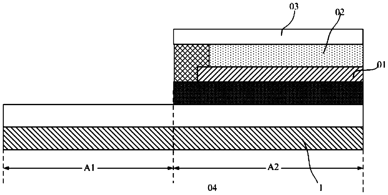
technical field [0001] The invention relates to the field of display technology, in particular to a display panel and a display device. Background technique [0002] Organic Light Emitting Diode (OLED) is one of the hot spots in the field of flat panel display research today. Compared with liquid crystal displays, OLED has the advantages of low energy consumption, low production cost, self-illumination, wide viewing angle and fast response speed. , OLEDs have begun to replace traditional Liquid Crystal Displays (LCDs) in the field of flat panel displays such as mobile phones, PDAs, and digital cameras. [0003] Since the organic light emitting display does not require a separate light source, it is relatively thin and can be used as a see-through display device that is transparent and capable of displaying images. See-through organic light-emitting display devices such as figure 1 as shown, figure 1 It is a schematic structural view of an existing see-through organic ligh...

Claims


Application Information

Patent Timeline
Patent Type & Authority Patents(China)
IPC IPC(8): H01L27/32H01L51/52
CPCH10K59/121H10K59/131H10K59/80522H10K59/80518H10K59/80524H10K59/122H10K50/818H10K50/824H10K50/828
Inventor 楼均辉
Owner SHANGHAI TIANMA MICRO ELECTRONICS CO LTD
Learn More