Coding circuit design method applied to optical fiber transmission

A technology of optical fiber transmission and encoding circuit, which is applied in the field of optical fiber transmission, can solve the problems of complex protocol design, high cost and large size of special chips, and achieve the effect of real-time uploading, simple design, and high-voltage isolation transmission requirements

Active Publication Date: 2018-01-12
THE 41ST INST OF CHINA ELECTRONICS TECH GRP
View PDF3 Cites 3 Cited by
  • Summary
  • Abstract
  • Description
  • Claims
  • Application Information

AI Technical Summary

Problems solved by technology

[0002] In the fields of high-voltage generation and testing such as power systems and program-controlled power systems, in order to ensure safety and reduce signal interference, and realize the isolation of low-voltage control and high-voltage output, optical fiber is usually used for isolated transmission. Optical fiber transmission has the characteristics of fast speed and high safety. Optical fiber transmission usually uses the standard 8B / 10B protocol for transmission. The design of this protocol is complex, and the balance problem needs to be considered. The cost of the dedicated chip is high and the volume is large.

Method used


Image

  • Coding circuit design method applied to optical fiber transmission
  • Coding circuit design method applied to optical fiber transmission
  • Coding circuit design method applied to optical fiber transmission

Examples


Embodiment Construction

[0024] The following will clearly and completely describe the technical solutions in the embodiments of the present invention with reference to the accompanying drawings in the embodiments of the present invention. Obviously, the described embodiments are only some, not all, embodiments of the present invention. Based on the embodiments of the present invention, all other embodiments obtained by persons of ordinary skill in the art without making creative efforts belong to the protection scope of the present invention.

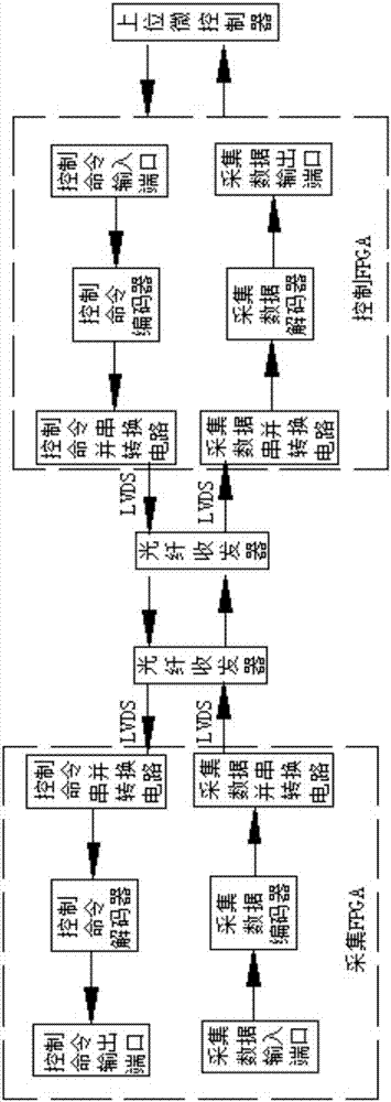
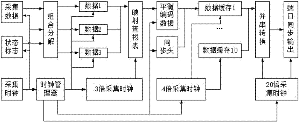
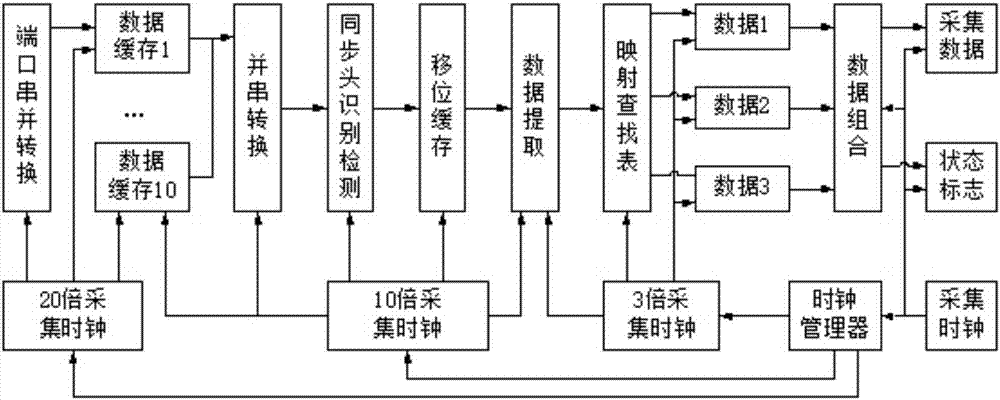
[0025] See Figure 1-Figure 3 , a coding circuit design method for optical fiber transmission, optical fiber transmission is to use optical fiber to connect the optical fiber transceiver connected to the acquisition FPGA and the optical fiber transceiver connected to the control FPCA to transmit signals, and the acquisition FPGA is internally provided with sequentially connected The acquisition data input port, the acquisition data encoder and the acquisition ...


PUM


Abstract

The invention discloses a coding circuit design method applied to optical fiber transmission. The method comprises coding processes and decoding processes: a coding process for collecting collection data in an FPGA and a decoding process for a control command, and a decoding process for controlling the collection data arranged in the FPGA and a coding process for the control command. According tothe method provided by the invention, the mode of combination of a synchronous head and a complete balanced code is used; the synchronous head and a transmission protocol are self-defined; a coder, decoder, a parallel-serial conversion circuit and a serial-parallel conversion circuit are designed, and thus bidirectional transmission of the high-voltage collection data and the low-voltage control command can be achieved through only connecting an external optical fiber transceiver; a hardware circuit is simple to design, and can completely replace a special chip and meet high voltage isolationtransmission requirements, and real-time uploading of the high-voltage end collection data and downloading of the low-voltage end control command are achieved.

Description

technical field [0001] The invention relates to the field of optical fiber transmission, in particular to a coding circuit design method for optical fiber transmission. Background technique [0002] In the fields of high-voltage generation and testing such as power systems and program-controlled power systems, in order to ensure safety and reduce signal interference, and realize the isolation of low-voltage control and high-voltage output, optical fiber is usually used for isolated transmission. Optical fiber transmission has the characteristics of fast speed and high safety. Optical fiber transmission usually uses the standard 8B / 10B protocol for transmission. The design of this protocol is complex, and the balance problem needs to be considered. The cost of the dedicated chip is high and the volume is large. Contents of the invention [0003] The technical problem to be solved by the present invention is to provide a coding circuit design method for optical fiber transmi...

Claims


Application Information

Patent Timeline
Patent Type & Authority Applications(China)
IPC IPC(8): H04B10/516H04B10/25H04L1/00
Inventor 栗永强布乃红凌云志李斌张永坡王文廷王俊王群王俊生彭海军
Owner THE 41ST INST OF CHINA ELECTRONICS TECH GRP
Why Eureka
Try Eureka