
Inertial separation microfluidic chip based on electrical impedance tomography (EIT) visual detection

An electrical impedance imaging and microfluidic chip technology, applied in the field of analysis and testing, can solve the problems of too much measurement data, influence of detection accuracy, influence of detection efficiency, etc., and achieve the effect of high detection accuracy and simple structure

Inactive Publication Date: 2018-01-16
NANJING UNIV OF AERONAUTICS & ASTRONAUTICS
View PDF1 Cites 6 Cited by
  • Summary
  • Abstract
  • Description
  • Claims
  • Application Information

AI Technical Summary

Problems solved by technology

Most of the pipe cross-sections of existing microfluidic chips use square cross-sections, the inertial separation efficiency is not high, and it has a certain impact on the detection accuracy; while the normal use of 12-electrode detection tends to cause too much measurement data, which affects the detection efficiency

Method used


Image

  • Inertial separation microfluidic chip based on electrical impedance tomography (EIT) visual detection
  • Inertial separation microfluidic chip based on electrical impedance tomography (EIT) visual detection
  • Inertial separation microfluidic chip based on electrical impedance tomography (EIT) visual detection

Examples


Embodiment Construction

[0015] The present invention will be further described below in conjunction with the accompanying drawings.

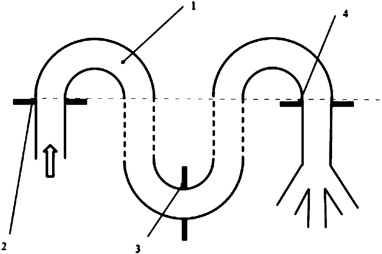
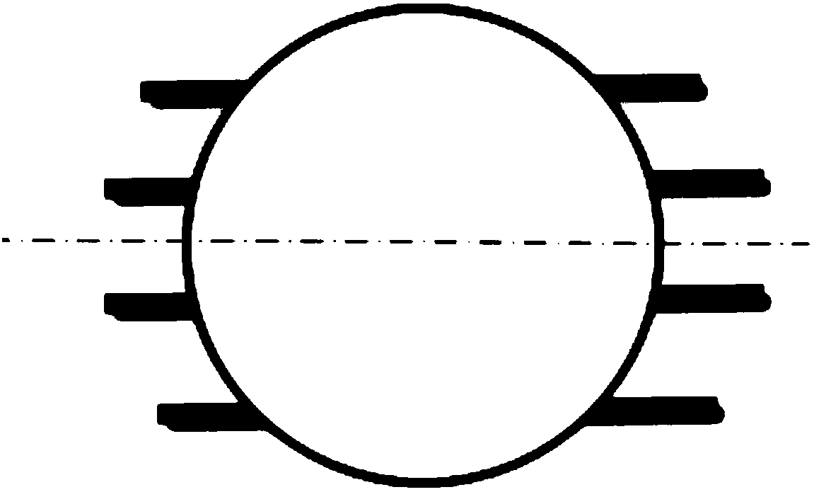
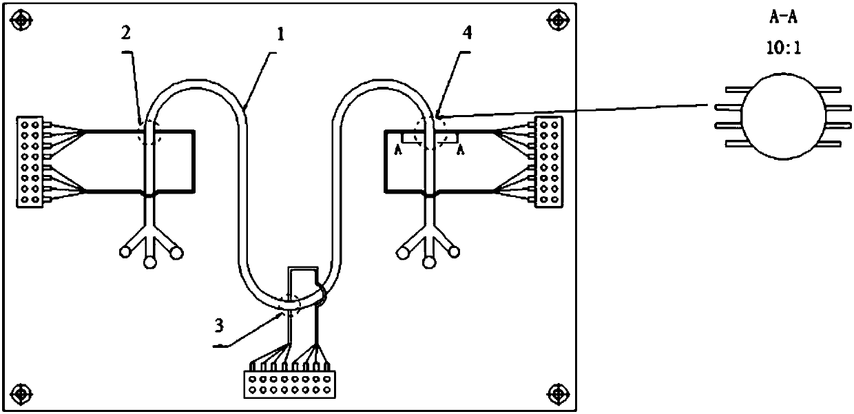
[0016] The inertial separation microfluidic chip based on electrical impedance imaging visual detection of the present invention consists of a tube 1 , a first electrode array group 2 , a second electrode array group 3 and a third electrode array group 4 . The first electrode array group 2 is arranged at the inlet of the tube 1 to detect the initial state of the solution. The second electrode array group 3 is arranged at the middle bend of the tube 1 for detecting the separation state there. The third electrode array group 4 is arranged at the outlet of the tube 1 to detect the end state of the solution.

[0017] The tube 1 has three inlets and three outlets, and the three inlets of the tube are arranged in the shape of a "claw", which can realize the proportioning of different components of the test solution. The three outlets of the tube are arranged in a "claw" sh...


PUM

PropertyMeasurementUnit
Radiusaaaaaaaaaa

Abstract

The invention discloses an inertial separation microfluidic chip based on electrical impedance tomography (EIT) visual detection. The microfluidic chip is composed of a tube, a first electrode array set, a second electrode array set, and a third electrode array set. The first electrode array set is arranged in the inlet of the tube. The second electrode array set is arranged in the middle bend ofthe tube. The third electrode array set is arranged in the outlet of the tube. The electrodes of the first electrode array set, the second electrode array set, and the third electrode array set are all connected to a pin socket. The provided microfluidic chip has a simple structure, is suitable for detecting a high concentration solution, and is non-invasive. The pipeline is in a round shape, andthus has a higher detection precision, compared with a square pipeline.

Description

Technical field: [0001] The invention relates to an inertial separation microfluidic chip based on visual detection of electrical impedance imaging, which belongs to the field of analysis and testing. Background technique: [0002] The inertial separation microfluidic chip is a device based on electrical impedance imaging technology, which uses its own structural characteristics to realize the inertial separation of solutions and image the process. It is widely used in medical testing and industrial testing. Most of the existing microfluidic chips use square cross-sections for the pipe cross-sections. The inertial separation efficiency is not high, and it has a certain impact on the detection accuracy; while the normal use of 12-electrode detection tends to cause too much measurement data, which affects the detection efficiency. [0003] Therefore, it is necessary to improve the prior art to solve the deficiencies of the prior art. Invention content: [0004] The present ...

Claims


Application Information

Patent Timeline
IPC IPC(8): B01L3/00
Inventor 姚佳烽姜祝鹏徐梓菲陈柏吴洪涛
Owner NANJING UNIV OF AERONAUTICS & ASTRONAUTICS
Learn More