
Slag removal system and method thereof

The technology of a slag discharge pipe and a slag discharge channel is applied in the field of coal gasification and can solve the problems of unsmooth slag discharge and unstable slag discharge.

Active Publication Date: 2018-01-16
ENN SCI & TECH DEV
View PDF4 Cites 4 Cited by
  • Summary
  • Abstract
  • Description
  • Claims
  • Application Information

AI Technical Summary

Problems solved by technology

[0004] The main purpose of the present invention is to provide a slag discharge system and method, which can improve the flow field distribution around the slag discharge pipe and avoid the occurrence of unstable slag discharge and unsmooth slag discharge caused by uneven flow field distribution. And can avoid safety hazards such as wear of the central jet tube

Method used


Image

  • Slag removal system and method thereof
  • Slag removal system and method thereof
  • Slag removal system and method thereof

Examples


Embodiment Construction

[0056] The following will clearly and completely describe the technical solutions in the embodiments of the present invention with reference to the accompanying drawings in the embodiments of the present invention. Obviously, the described embodiments are only some, not all, embodiments of the present invention. Based on the embodiments of the present invention, all other embodiments obtained by persons of ordinary skill in the art without making creative efforts belong to the protection scope of the present invention.

[0057] In describing the present invention, it is to be understood that the terms "center", "upper", "lower", "front", "rear", "left", "right", "vertical", "horizontal", The orientations or positional relationships indicated by "top", "bottom", "inner", "outer", etc. are based on the orientations or positional relationships shown in the drawings, and are only for the convenience of describing the present invention and simplifying the description, rather than in...


PUM


Abstract

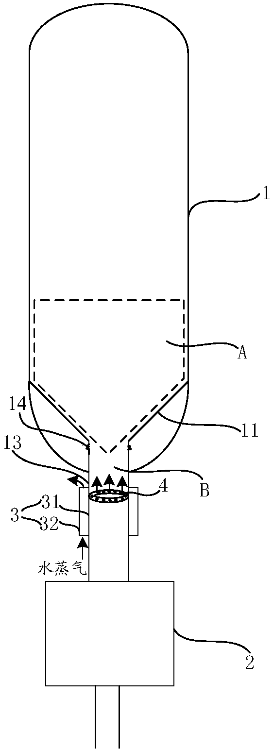
The invention relates to the field of coal gasification technology, especially to a slag removal system and a method thereof. According to the invention, distribution of flow field around a slag removal pipe can be improved, instability and obstruction of slag removal due to uneven distribution of flow field are avoided, and potential safety hazards such as abrasion of a central jet pipe, etc. canbe avoided. The slag removal system comprises a gasifier, the bottom of which is provided with a gas distribution plate. A gas distribution plate zone is above the gas distribution plate. The bottomof the gas distribution plate extends downward to provide with a slag removal pipe, which penetrates through the bottom of the gasifier. A columnar slag removal channel which is communicated with thegas distribution plate zone is formed at the bottom of the gasifier and is communicated with a slag hopper system through a connection pipe nipple. One end of the connection pipe nipple, close to theslag removal pipe, is provided with an annular gas distributor, which is used for distributing gas to the gas distribution plate zone through the columnar slag removal channel. A swirl flow field is formed in the gas distribution plate zone, and ash and slag fall down under the action of the swirl flow field and are discharged through the slag hopper system.

Description

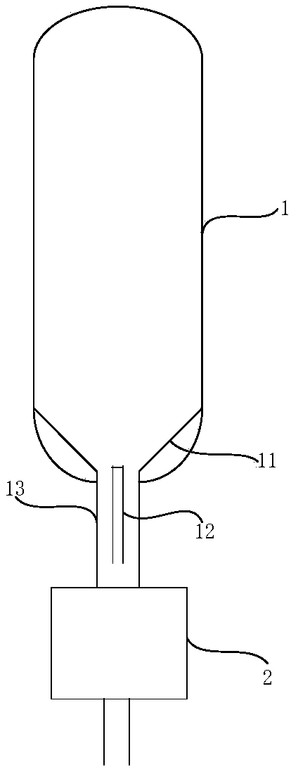
technical field [0001] The invention relates to the technical field of coal gasification, in particular to a slag discharge system and method. Background technique [0002] Coal catalytic gasification technology is an important way of clean and efficient utilization of coal, and it is one of the most efficient gasification technologies for coal-to-natural gas. That is, coal is gasified with a gasifying agent composed of water vapor, hydrogen and carbon monoxide under a certain pressure and temperature under the catalytic action of a catalyst to generate high-concentration methane. [0003] The catalytic coal gasification process is usually carried out in a fluidized bed gasifier, see figure 1 As shown, the bottom of the fluidized bed gasification furnace 1 is provided with a conical gas distribution plate 11 and a central jet pipe 12, and the bottom of the conical gas distribution plate 11 is extended downward with a slagging pipe 13, and the slagging pipe 13 passes throug...

Claims


Application Information

Patent Timeline
IPC IPC(8): C10J3/34C10J3/52
Inventor 毛燕东芦涛刘雷李克忠
Owner ENN SCI & TECH DEV
Learn More