
A design and construction method for protecting an underground high-voltage cable box culvert across a foundation pit

A technology of high-voltage cables and construction methods, which is applied in the field of construction engineering, and can solve problems such as creep of wire ropes, accidents caused, and uneven stress on wire ropes

Active Publication Date: 2019-04-12
CHINA RAILWAY 24TH BUREAU GRP
View PDF4 Cites 0 Cited by
  • Summary
  • Abstract
  • Description
  • Claims
  • Application Information

AI Technical Summary

Problems solved by technology

"However, the cable box culvert protection method described in this invention requires that there be a shelving girder parallel to the location of the box culvert, which is not suitable for the protection of cable box culverts on tunnel construction passages without shelving girders. At the same time, this technology uses steel wire rope Suspension protection is carried out. Long-term suspension under heavy loads is likely to cause creep of the steel wire rope. In addition, due to the frequent entry and exit of transportation equipment in the field construction state, a little carelessness may touch the wire rope of the suspension device, causing the box culvert to move left and right. Shaking, while the steel wire rope may experience uneven stress, increased local stress, and breakage. In severe cases, accidents may occur, endangering the lives of construction workers and wasting social wealth.

Method used


Image

  • A design and construction method for protecting an underground high-voltage cable box culvert across a foundation pit
  • A design and construction method for protecting an underground high-voltage cable box culvert across a foundation pit
  • A design and construction method for protecting an underground high-voltage cable box culvert across a foundation pit

Examples


Embodiment Construction

[0099] The present invention will be described in detail below in conjunction with specific embodiments. The following examples will help those skilled in the art to further understand the present invention, but do not limit the present invention in any form. It should be noted that those skilled in the art can make several modifications and improvements without departing from the concept of the present invention, and these all belong to the protection scope of the present invention.

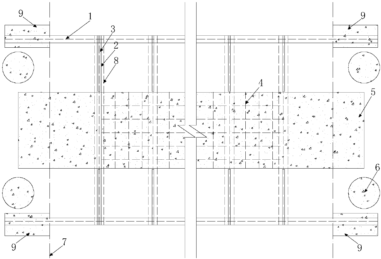
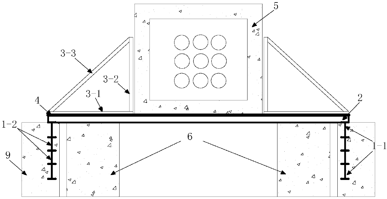
[0100] Taking a light rail line in Chongqing as an example, the cable box culvert involved is a 110KV high-voltage cable box culvert. ; Located on the tunnel entrance and exit construction passage, buried at a depth of about 1m underground. The retaining piles arranged on both sides of the construction passage have a diameter of 70cm and a spacing of 210cm, and are located on both sides of the cable box culvert.

[0101] In order to prevent the cable box culvert from being suspended due to the...


PUM


Abstract

The invention provides a design and construction method for an underground high-voltage cable box culvert for protecting and crossing a foundation pit. The method comprises the steps of collecting cable box culvert data, and determining the integrality of the cable box culvert; staking out in survey, and determining the positions of the cable box culvert and a fender post; excavating soil bodies in the two sides of the cable box culvert, and preinstalling a steel I-beam; hollowing out soil in a lower groove in the cable box culvert, and arranging connecting rods; welding triangular square steel frames to the two ends of each connecting rod; lifting the steel I-beam, and performing anchoring; after concrete is hardened, hollowing out soil bodies among grooves, welding reinforced steel bar meshes between the connecting rods below the cable box culvert, and spraying concrete for anchoring. The purpose that the underground high-voltage cable box culvert is embedded on a tunnel constructionchannel is achieved, the safety of the cable box culvert is more effectively ensured by using the steel I-beam for supporting, the relocating work of the cable box culvert is avoided, in the whole construction process, the time limit of a project is shortened, the construction efficiency is improved, the removal charge is saved, the construction cost is lowered, and the influence on surrounding residents is relieved.

Description

technical field [0001] The invention relates to a method in the technical field of construction engineering, in particular to a design and construction method for protecting an underground high-voltage cable box culvert spanning a foundation pit with a cast-in-place support. Background technique [0002] In recent years, with the acceleration of my country's urbanization process and the rapid growth of urban population, urban ground transportation systems have become increasingly congested, and urban rail transportation has developed rapidly in large and medium-sized cities. In the construction of urban rail transit, urban underground pipelines such as underground high-voltage cables are often encountered. During the construction process, some construction units forced construction in order to catch up with the construction period, which is very likely to cause large deformation or damage to urban underground pipelines such as underground high-voltage cables. Underground pi...

Claims


Application Information

Patent Timeline
Patent Type & Authority Patents(China)
IPC IPC(8): E02D31/00E02D29/045H02G9/08
Inventor 张正朱亮来吴庆润程波金剑曾毅丁鹏飞刘新功陈红邓江陈霄周祯淳张建启陈柯霖沈水龙吕海敏
Owner CHINA RAILWAY 24TH BUREAU GRP
Learn More