
Component for rock breaking system

A component and rock-breaking technology, applied in the direction of borehole/well components, driving device for rotary combined drilling, drilling equipment and methods, etc., can solve problems such as interference of measurement results

Inactive Publication Date: 2018-01-16
SANDVIK MINING & CONSTR OY
View PDF10 Cites 0 Cited by
  • Summary
  • Abstract
  • Description
  • Claims
  • Application Information

AI Technical Summary

Problems solved by technology

However, subjecting rock-breaking system components to external magnetic fields while measuring stress waves can cause disturbances in the measurement results, regardless of instrument configuration

Method used


Image

  • Component for rock breaking system
  • Component for rock breaking system
  • Component for rock breaking system

Examples


Embodiment Construction

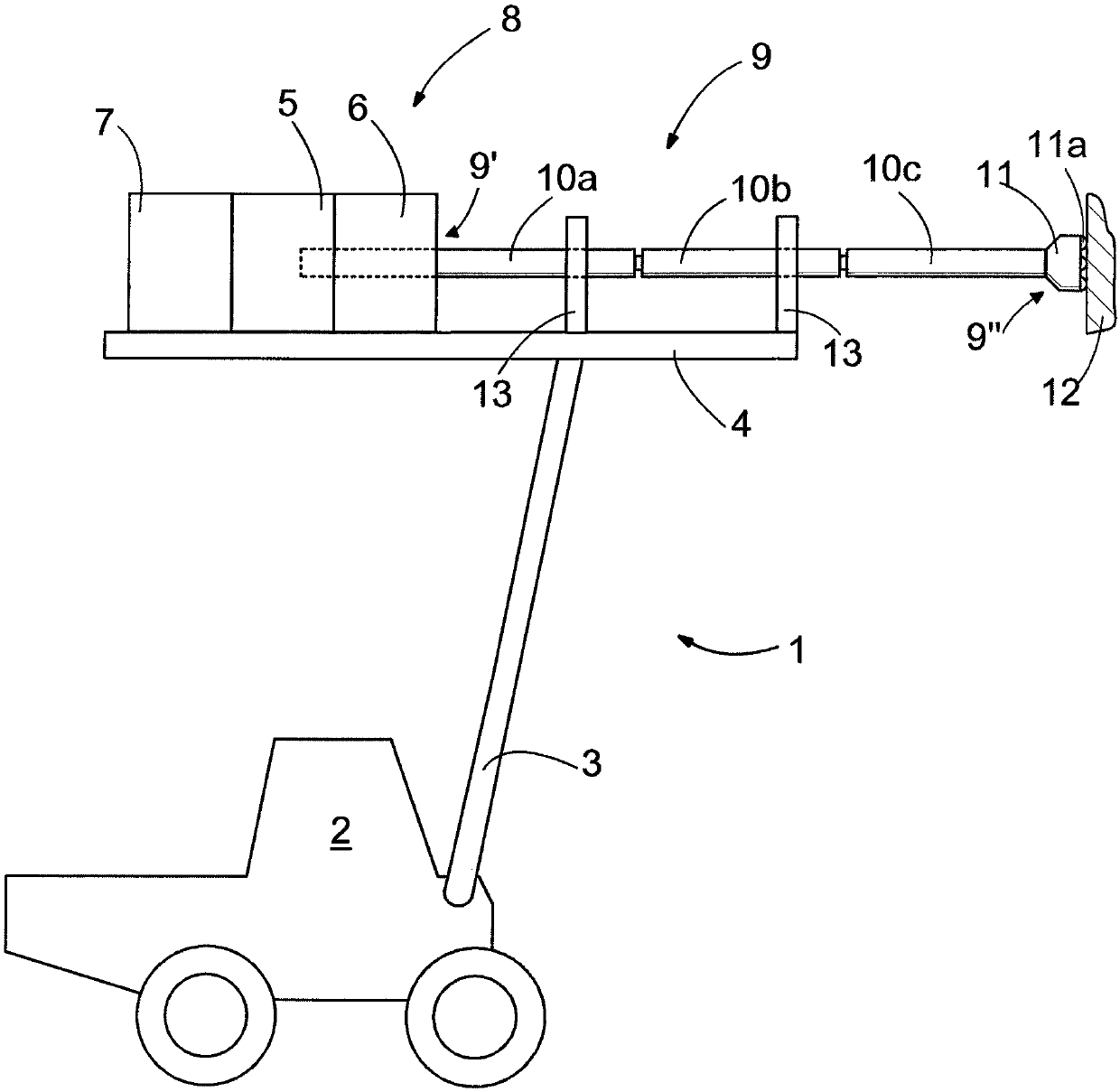
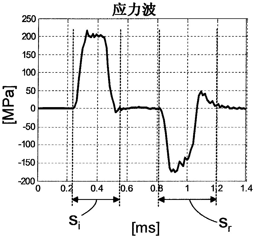
[0020] Rock breaking may be performed by drilling a hole in the rock by a rock drilling machine. Alternatively, the rock can be broken by a breaking hammer. In this context, the term "rock" should be interpreted broadly to also cover pebbles, rocky material, encrustations and other relatively hard materials. Rock drills and breakers include impact mechanisms that provide impact pulses to the tool directly or through an adapter. The shock pulse generates a stress wave that propagates in the tool. When the stress wave reaches the end of the tool facing the rock to be drilled, the tool penetrates the rock due to the influence of the stress wave. Some of the energy of the stress wave may be reflected back as a reflected wave that propagates in the tool in the opposite direction (ie, towards the impact mechanism). Depending on the situation, the reflected waves may contain only compressive stress waves or tensile stress waves. However, reflected waves generally include a tensil...


PUM

PropertyMeasurementUnit
coercivityaaaaaaaaaa

Abstract

A component for a rock breaking system is magnetized into a state of remanent magnetization. The remanent magnetization of the component has a predetermined varying magnetization profile relative to geometry of the component, the varying magnetization profile describing varying magnetization intensity in the component relative to the geometry of the component.

Description

technical field [0001] The present invention relates to an assembly for a rock breaking system of which it is a part, but which can also be applied to measure stresses, vibrations or forces occurring in the rock breaking system during rock breaking. Background technique [0002] In controlling rock breaking, stresses occurring in the rock breaking system during rock breaking can be measured and used. FI69680 and US4,671,366 disclose an example of measuring stress waves occurring during rock breaking and using the measured stress waves to control the operation of a rock breaking device. DE19932838 and US 6,356,077 disclose a signal processing method and device for determining stress wave parameters by measuring stress wave induced magnetoelastic changes in components of a rock breaking system subjected to shock loading. [0003] For example, in US 6,356,077, stress waves occurring during rock breaking are measured by measuring changes in the magnetic properties of rock break...

Claims


Application Information

Patent Timeline
Patent Type & Authority Applications(China)
IPC IPC(8): E21B1/00G01L5/00
CPCE21B1/02E21B7/022E21B7/025E21B49/003E21B47/007E21B6/02E21B7/02
Inventor 努拉·卡莱沃韦萨·乌伊托托墨·皮理楠安蒂·科斯基迈基
Owner SANDVIK MINING & CONSTR OY
Learn More