Engine and cam shaft thereof and manufacturing method of cam shaft

A manufacturing method and camshaft technology, applied to engine components, machines/engines, mechanical equipment, etc., can solve the problems of complex camshaft structure, complicated manufacturing process, limited transmission torque, etc., and achieve reduced manufacturing time and improved manufacturing process Effects of simplification, axial size reduction

Inactive Publication Date: 2018-01-16
SHANGHAI UNIVERSOON AUTOPARTS CO LTD
View PDF10 Cites 1 Cited by
  • Summary
  • Abstract
  • Description
  • Claims
  • Application Information

AI Technical Summary

Problems solved by technology

[0008] The problem solved by the present invention is that the existing camshaft has complex structure, complex manufacturing process, long time consumption, high cost and limited transmission torque

Method used


Image

  • Engine and cam shaft thereof and manufacturing method of cam shaft
  • Engine and cam shaft thereof and manufacturing method of cam shaft
  • Engine and cam shaft thereof and manufacturing method of cam shaft

Examples


no. 1 example

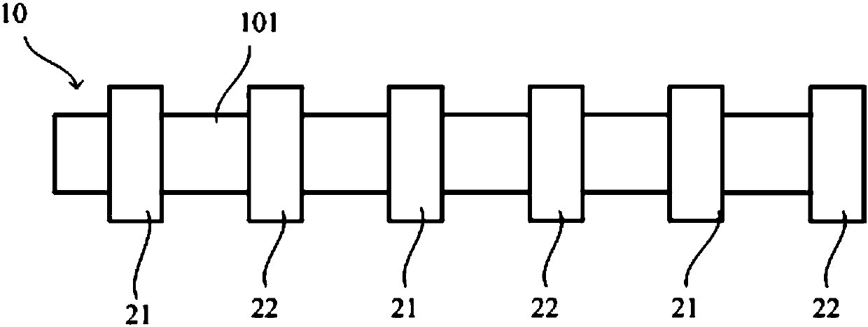
[0074] Embodiments of the present invention provide a camshaft, such as figure 1 As shown, it includes a mandrel 10 and a plurality of cams sleeved on the mandrel 10 . The plurality of cams include a first cam 21 and a second cam 22 . Wherein, the first cam 21 and the second cam 22 are sleeved on the outside of the core shaft 10 and arranged at intervals along the axial direction.

[0075] Such as figure 1 A camshaft with six cams is exemplarily shown, and each cam on the camshaft corresponds to a cylinder. The first cam 21 and the second cam 22 are connected to the core shaft 10 in a rotationally fixed manner, and both rotate synchronously. The first cam 21 and the second cam 22 are respectively used to drive different valves. figure 1 In the illustrated embodiment, the first cam 21 and the second cam 22 are adjacent without other cams in between. In other embodiments, other cams may also be provided between the first cam 21 and the second cam 22 .

[0076] The mandrel 1...

no. 2 example

[0085] This embodiment provides a camshaft. The camshaft of this embodiment changes the structures of the first cam 21 and the second cam 22 on the basis of the first embodiment.

[0086] refer to Figure 5 As shown, at least one of the first cam 21 and the second cam 22 includes a first part 201 and a second part 202 arranged in the axial direction. direction, radial direction and axial direction are all fixed on the mandrel 10, that is, the first part 201, the second part 202 and the mandrel 10 are completely fixed. Relative movement occurs between 10. Wherein, it can be set that all the cams sleeved on the mandrel 10 include the first part and the second part; it can also be set that some cams sleeved on the mandrel include the first part and the second part, and The rest of the cams can be integrally formed cams.

[0087] exist Figure 5 In the shown embodiment, the first cam 21 and the second cam 22 sleeved on the mandrel 10 both include the first part 201 and the sec...

no. 3 example

[0101] This embodiment provides an engine, including the camshaft described in the above-mentioned first embodiment or the second embodiment, and the first valve and the second valve, wherein the first cam 21 is used to drive the first valve but not drive the second valve. Two valves, the second cam 22 is used to drive the second valve but not the first valve.

[0102] The first valve and the second valve may be valves of the same cylinder, or valves of different cylinders.

[0103] When the cam includes the first part 201 and the second part 202, the first part 201 and the second part 202 of the same cam drive at least the same valve.


PUM


Abstract

Provided are an engine and a cam shaft thereof and a manufacturing method of the cam shaft. The cam shaft comprises a central spindle, first cams and second cams, wherein the central spindle is provided with axial holes and matching segments, and the outer peripheral cross section of the matching segment at any axial position is polygonal; the first cams and the second cams are axially arranged onthe matching segments of the central spindle in a sleeving mode at intervals, the cross sections of the inner periphery surfaces of the first cams and the second cams are both polygonal, and each matching segment axially extends at least from the corresponding first cam to the corresponding second cam. Compared with existing cam shafts connected by adopting splines, the cam shaft can transmit larger torque and is simpler in structure, the manufacturing technology of the cam shaft is simplified, the manufacturing time consumption is reduced, and the cost is lowered.

Description

technical field [0001] The invention relates to the field of automobile engines, in particular to an engine, a camshaft thereof, and a method for manufacturing the camshaft. Background technique [0002] The valve mechanism of the engine is responsible for providing the cylinder with the fresh air necessary for the combustion of gasoline and discharging the exhaust gas after combustion. [0003] The camshaft is a key part of the gas distribution structure. The engine is equipped with an intake camshaft and an exhaust camshaft. Each camshaft has a core shaft and a cam sleeved on the core shaft. The core shaft and the engine crankshaft pass through a chain or Belt transmission connection, the mandrel and the cam rotate synchronously. Among them, the cam of the intake camshaft is used to drive the intake valve of the engine to open and close, and the cam of the exhaust camshaft is used to drive the exhaust valve of the engine to open and close. [0004] In the existing engine...

Claims


Application Information

Patent Timeline
Patent Type & Authority Applications(China)
IPC IPC(8): F01L1/047
Inventor 奚勇杨洲朱松
Owner SHANGHAI UNIVERSOON AUTOPARTS CO LTD
Why Eureka
Try Eureka