Portable laser spot detection device and system

A laser spot and detection device technology, which is applied to measurement devices, optical devices, and electrical radiation detectors for photometry, etc., can solve the problems of time-consuming, time-consuming and labor-intensive operations, and cannot be quickly deployed, and can evaluate the performance of equipment. , The effect of detection is simple and fast, and it is convenient for event tracing

Pending Publication Date: 2018-01-16
BEIJING AOPTEK SCI +1
View PDF0 Cites 5 Cited by
  • Summary
  • Abstract
  • Description
  • Claims
  • Application Information

AI Technical Summary

Problems solved by technology

[0006] 1. The integration of equipment has not been realized, and only spare parts can be used for temporary construction. The integration, low volume and large size, long operation time, cannot be quickly deployed, and the failure rate is high, which cannot meet the application requirements
[0007] 2. The software used is not special-purpose software, usually a supporting demonstration software for the camera. The supporting software for the camera is only used to control the parameters of the camera and complete the basic image acquisition function, not including the image processing function module, which is complicated to use and cumbersome to operate.
[0008] 3. The software used does not have the analysis function. The analysis operation of the captured image requires the help of professional image processing software, and professional software is often full-featured, which requires high operating skills of the operator and is time-consuming and laborious.

Method used


Image

  • Portable laser spot detection device and system
  • Portable laser spot detection device and system
  • Portable laser spot detection device and system

Examples


Embodiment 1

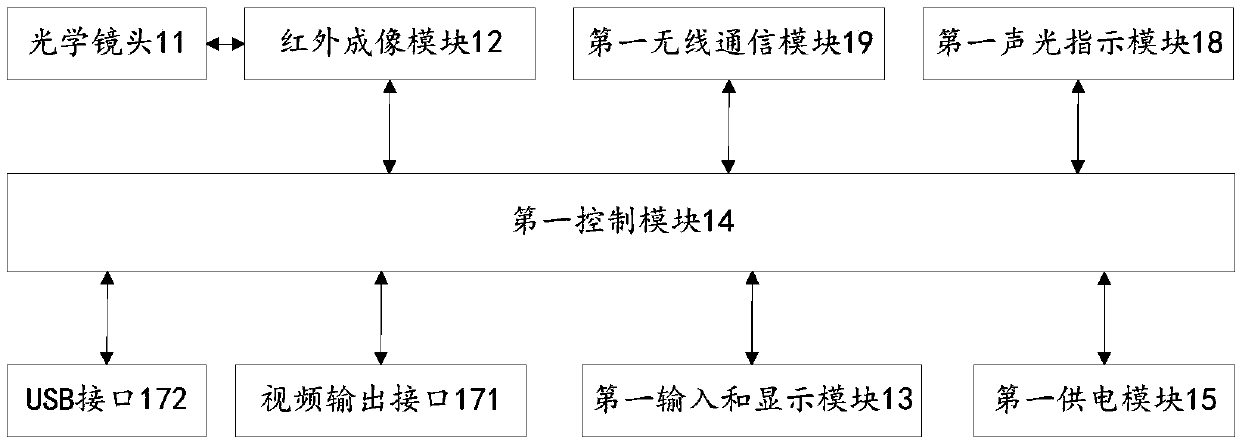
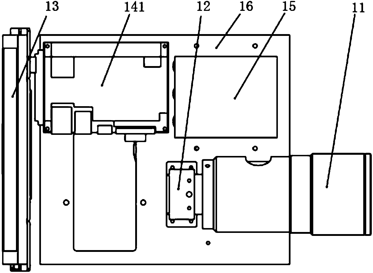
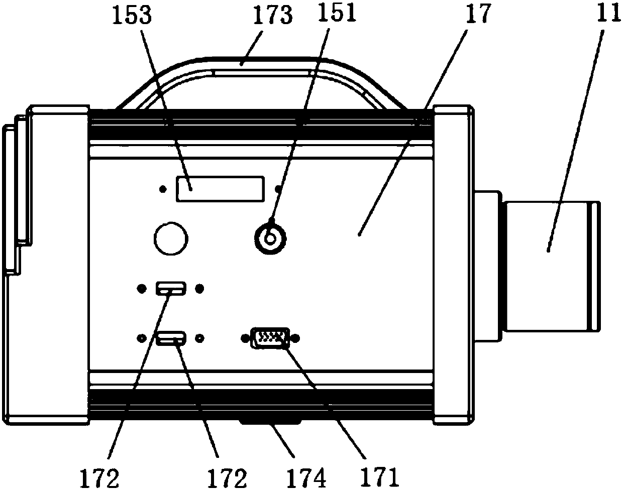
[0059] In the target shooting test of the laser guidance equipment, the laser pointer 3 needs to irradiate the target 4 to form a laser spot 5 on the target 4, and the laser guidance equipment uses this spot as the target to track and strike. In order to realize the monitoring, analysis and record storage of the laser spot 5 , the present invention provides a portable laser spot detection device, including the detection device 1 . figure 1 It is a structural block diagram of the portable laser spot detection device 1 provided by the embodiment of the present invention. For the sake of simplification, only those elements related to the subject of the text are shown. The overall detection device 1 can have many other configurations and many other types can be used equipment. Such as figure 1 As shown, the detection device 1 adopts an integrated structure, and the detection device 1 includes an optical lens 11 , an infrared imaging module 12 , a first input and display module 13...

Embodiment 2

[0091] The present invention provides a portable laser spot detection system, including the portable laser spot detection device provided in Embodiment 1 and a remote control terminal 2 .


PUM


Abstract

The invention discloses a portable laser spot detection device. The device includes an optical lens, an infrared imaging module, a first input and display module, a first control module and a first power supply module; the optical lens, the infrared imaging module, the first control module and the first power supply module are all arranged on a bottom plate; the front end of the optical lens extends out of a shell; the rear end of the optical lens is connected with the infrared imaging module; the infrared imaging module is connected with the first control module; the first control module is connected with the first input and display module; the infrared imaging module and the first control module are both accommodated in the shell; and the first input and display module is arranged at theouter side the shell. The invention also provides a portable laser spot detection system. The integration and systematization of the detection device is realized. With the portable laser spot detection device and system of the invention adopted, laser spot images can be monitored and analyzed in real time. The portable laser spot detection device and system are simple, quick and convenient in use.

Description

technical field [0001] The invention relates to the technical field of image detection, in particular to a portable laser spot detection device and system. Background technique [0002] Laser guidance refers to the guidance technology that uses a laser pointer to emit a laser beam to a target, uses a receiver to receive the laser beam reflected from the target, and guides the guidance device to fly to the target. Because of its superior characteristics such as high guidance precision, strong anti-interference ability, simple structure, and low cost, it is widely used in laser guidance equipment. For example: laser-guided bombs (such as the US "Paveway"), laser-guided missiles (such as the US "Haierfa" anti-tank missiles) and laser-guided artillery shells (such as "Copperhead"), etc. [0003] In the target shooting test of laser-guided equipment, it is necessary to irradiate the target with a laser pointer to form a laser spot on the target. The laser-guided equipment uses t...

Claims


Application Information

Patent Timeline
Patent Type & Authority Applications(China)
IPC IPC(8): G01B11/00G01J1/42
Inventor 谷建纯张喆民王伟志常俏魏天虎赵洪建钟星辉苑静
Owner BEIJING AOPTEK SCI
Why Eureka
Try Eureka