Polymer concrete pipe production line

A production line, polymer technology, applied in tubular articles, applications, household appliances, etc., can solve problems such as shedding, limited pressure bearing performance, pipeline damage, etc., to reduce the phenomenon of erosion, enhance the overall adhesion, and improve the yield. Effect

Active Publication Date: 2018-01-19
山东土大力管道工程有限公司
View PDF4 Cites 3 Cited by
  • Summary
  • Abstract
  • Description
  • Claims
  • Application Information

AI Technical Summary

Problems solved by technology

[0002] Existing underground water delivery pipelines generally use reinforced concrete pipelines, which are mainly responsible for water delivery functions such as drinking water, sewage, rainwater or farmland irrigation. However, existing reinforced concrete pipelines have many shortcomings. Damage or fall off, causing water leakage is more common, and when buried in the soil or transporting corrosive sewage, the concrete pipeline will be gradually eroded, causing pipeline damage. After the concrete pipeline is damaged, it needs to be replaced or repaired, all of which need to be interrupted During the water delivery process, the buried pipeline needs to be excavated, and the engineering volume is relatively large. The post-maintenance of the reinforced concrete pipeline requires a lot of manpower and material resources. The existing reinforced concrete pipeline production line basically includes aggregate transportation, water transportation and mixing. Reinforced concrete forming pipes are formed after post-curing. Such a production line is not suitable for producing new polymer concrete pipe production lines. Therefore, when developing new types of concrete pipes, the production line needs to be improved

Method used


Image

  • Polymer concrete pipe production line
  • Polymer concrete pipe production line
  • Polymer concrete pipe production line

Examples


Embodiment Construction

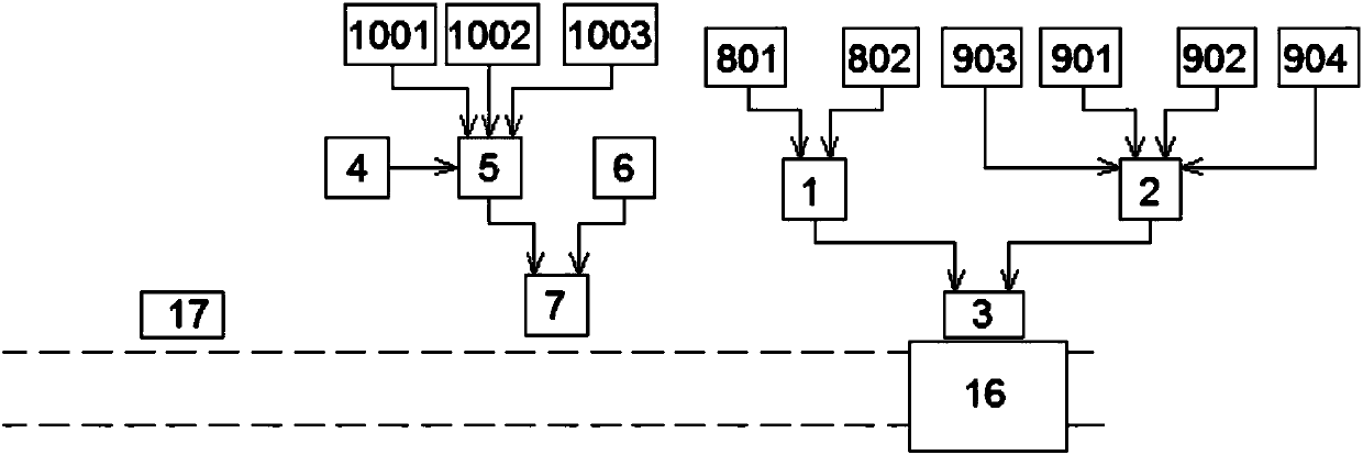
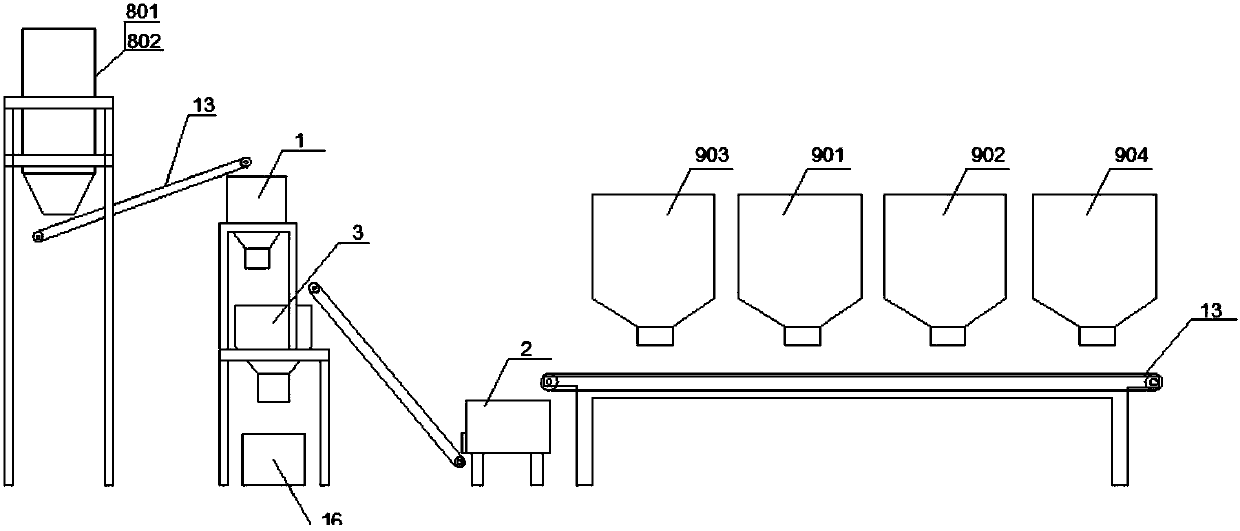
[0021] The invention relates to a polymer concrete pipeline production line, comprising an aggregate supply mechanism, a liquid material supply mechanism, a mixing mechanism and a pouring mechanism. The input ends of the mixing mechanism are respectively corresponding to the output ends of the aggregate supply mechanism and the liquid material supply mechanism. The output end of the mixing mechanism is connected with the input end of the pouring mechanism. The aggregate supply mechanism includes a first mixer 1 and a second mixer 2, and a first mixer 1 and a second mixer arranged in parallel The output ends of 2 are connected to the input end of the third mixer 3. The input end of the first mixer 1 is connected to a group of coarse bins arranged in parallel, and the input end of the second mixer 2 is connected to a group of powders arranged in parallel. Silo; the liquid material supply mechanism includes a set of auxiliary tank, resin tank 4, transfer tank 5, auxiliary material ...


PUM


Abstract

The invention relates to a polymer concrete pipe production line. The polymer concrete pipe production line comprises an aggregate feeding mechanism, a liquid material feeding mechanism, a material mixing mechanism and a pouring mechanism; the input end of the material mixing mechanism is connected with the output end of the aggregate feeding mechanism and the output end of the liquid material feeding mechanism, and the output end of the material mixing mechanism is connected with the input end of the pouring mechanism; the aggregate feeding mechanism comprises a first mixing machine and a second mixing machine which are arranged in parallel, the output ends of the first mixing machine and the second mixing machine are connected with the input end of a third mixing machine, the input end of the first mixing machine is connected with a coarse material bin, and the input end of the second mixing machine is connected with a powdery material bin; the liquid material feeding mechanism comprises an auxiliary tank, a resin tank, a transferring tank, an ingredient tank and a mixing tank, the output ends of the auxiliary tank and the resin tank are connected with the input end of the transferring tank, and the output ends of the transferring tank and the ingredient tank are connected with the input end of the mixing tank; and the pouring mechanism comprises a pouring die and a driving mechanism of the pouring die, and a movable hopper is arranged among the output end of the third mixing machine, the output end of the mixing tank and the input end of the pouring die.

Description

Technical field [0001] The invention relates to the technical field of pipeline production, in particular to a polymer concrete pipeline production line. Background technique [0002] Existing underground water pipelines generally use reinforced concrete pipes, which are mainly responsible for water delivery functions such as drinking water, sewage, rainwater or farmland irrigation. However, the existing reinforced concrete pipelines have many shortcomings. First of all, the pressure-bearing performance is limited, and the concrete is easy to crack. Damaged or falling off, causing water leakage is more common, and when buried in the soil or transporting corrosive sewage, the concrete pipeline will gradually be eroded, causing pipeline damage. After the damaged concrete pipeline needs to be replaced or repaired, it needs to be interrupted The water delivery process and the need to excavate buried pipelines require a large amount of work. The later maintenance of reinforced concret...

Claims


Application Information

Patent Timeline
Patent Type & Authority Applications(China)
IPC IPC(8): B29C39/10B29C39/26B29B7/74C04B26/02B29K503/08B29L23/00
Inventor 温振刚李先众谢云龙
Owner 山东土大力管道工程有限公司
Why Eureka
Try Eureka