Continuous fiber reinforced composite propeller layer lay-up design and preparation method
A reinforced composite material and continuous fiber technology, applied in the field of materials, can solve the problems of high price and low production efficiency, and achieve the effect of improving production efficiency, improving product quality and ensuring continuity
- Summary
- Abstract
- Description
- Claims
- Application Information
AI Technical Summary
Problems solved by technology
Method used
Image
Examples
preparation example Construction
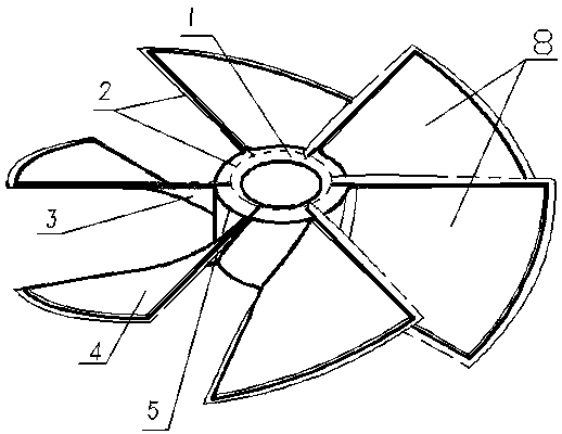
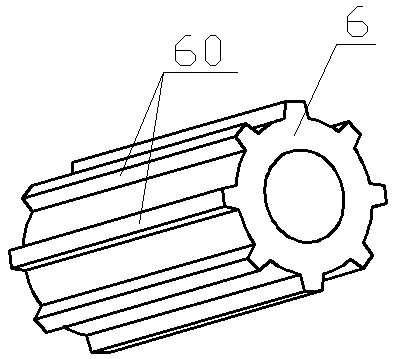
[0044] The blade 8 of the present invention is formed by stacking continuous fiber prepreg sheets, such as Figure 4 As shown, the hub 1 is composed of a metal insert 6 and multiple layers of continuous fiber prepreg sheets wound outside the metal insert 6 . A continuous fiber reinforced composite propeller layup design and preparation method, comprising the following steps:
[0045] Step 1. Blade geometry processing and blade shape design
[0046] (1) Geometric processing of blades:
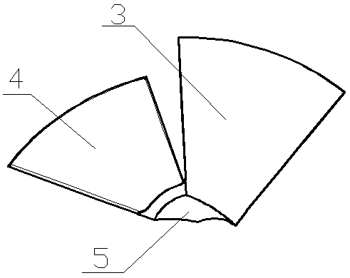
[0047] Extract the geometric mid-plane 2 of the propeller as the reference surface for propeller design; define the part of the blade 8 above the geometric mid-plane 2 as the upper half 3 of the blade, and define the part of the blade 8 below the geometric mid-plane 2 as the lower half of the blade Section 4, as in figure 1 As shown; the part of the propeller hub located between two adjacent blades 8 and outside the reference curved surface (geometric midplane 2) is defined as a continuous ar...
Embodiment 1
[0068] A continuous fiber reinforced composite propeller layup design and preparation method, comprising the following steps:
[0069] Take a geometrical longitudinal section of the propeller along a plane passing through the midline of the three-blade propeller blades (eg Figure 5 As shown), the thickness of the blade near the hub is 26.67mm, the thickness of the blade near the outer edge is 6.72mm, and the radius of the propeller blade is 200mm.
[0070] Extract the middle surface layer by 3D design software, extract the middle surfaces of two adjacent blades for rotation, and perform Boolean operations with the propeller to obtain a 3D map of the preformed blade, as shown in figure 1 shown.
[0071]The measured area with the largest thickness of the preformed blade is a continuous area, which is about 18.24 mm. The unidirectional fiber prepreg is selected, the reinforced phase is T700 unidirectional carbon fiber, the resin is tough epoxy resin, and the average thickness ...
Embodiment 2
[0079] A continuous fiber reinforced composite propeller layup design and preparation method, comprising the following steps:
[0080] The propeller is geometrically longitudinally sectioned along the plane passing through the midline of the three-bladed propeller blades. The thickness of the blade near the hub is 64.73mm, the thickness of the blade near the edge is 22.6mm, and the radius of the propeller blade is 400mm.
[0081] The mid-surface layer is extracted by 3D design software, and the mid-surfaces of two adjacent blades are extracted for rotation, and Boolean operations are performed with the propeller to obtain a 3D map of the preformed blade.
[0082] The region with the largest thickness of the preformed blade is the blade root region, with a thickness of 32.37mm, and the thickness of the continuous region is 28.44mm. The unidirectional fiber prepreg is selected as the reinforced phase of T700 carbon fiber fabric, and the resin is tough epoxy resin with an average...
PUM
| Property | Measurement | Unit |
|---|---|---|
| Diameter | aaaaa | aaaaa |
| Thickness | aaaaa | aaaaa |
| Thickness | aaaaa | aaaaa |
Abstract
Description
Claims
Application Information
 - R&D
- Intellectual Property
- Life Sciences
- Materials
- Tech Scout
- Unparalleled Data Quality
- Higher Quality Content
- 60% Fewer Hallucinations
Browse by: Latest US Patents, China's latest patents, Technical Efficacy Thesaurus, Application Domain, Technology Topic, Popular Technical Reports.
© 2025 PatSnap. All rights reserved.Legal|Privacy policy|Modern Slavery Act Transparency Statement|Sitemap|About US| Contact US: help@patsnap.com


