Cooling circulation system for locomotive

A circulation system and locomotive technology, applied in the direction of cooling/ventilation of locomotives, substations/switchgear, etc., can solve the problems of inconvenient equipment layout in the machine room, increase the heat dissipation load of the machine room, and low cooling efficiency, so as to achieve the convenience of the machine room Equipment layout, cabinet size reduction, and high heat dissipation efficiency

Active Publication Date: 2018-01-19
ZHUZHOU ELECTRIC LOCOMOTIVE CO LTD
View PDF7 Cites 10 Cited by
  • Summary
  • Abstract
  • Description
  • Claims
  • Application Information

AI Technical Summary

Problems solved by technology

[0003] This kind of heat dissipation method has the following disadvantages: (1) the air temperature in the mechanical room is high, and the air is sucked from the mechanical room to cool the electrical components in the train power supply cabinet and other cooling equipment, and the cooling efficiency is low; (2) the train power supply cabinet and other The heat generated by the electrical components of the cooling equipment is directly dissipated in the machine room, increasing the heat dissipation load of the machine room; (3) The train power supply cabinet and other cooling equipment are equipped with fans and air ducts, which are large in size and are not convenient for equipment layout in the machine room

Method used


Image

  • Cooling circulation system for locomotive

Examples


Embodiment 1

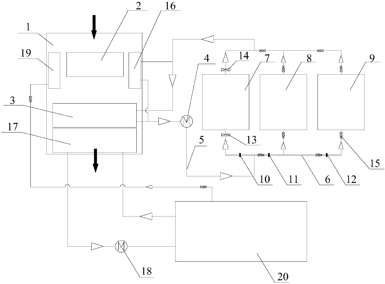
[0050] Such as figure 1 As shown, the present invention discloses a cooling cycle system for a locomotive. The cooling cycle system for a locomotive includes a cooling tower 1 , a main cooling fan 2 , a water radiator 3 , a water pump 4 , an output water pipe 5 and a first pipe 6 .

[0051] Wherein, the main cooling fan 2 and the water radiator 3 are all arranged in the cooling tower 1 outside the car body, the main cooling fan 2 can blow the cold wind at the inlet of the cooling tower 1 to the water radiator 3, and the inlet of the water pump 4 and the water radiator The outlet of the device 3 is connected, and the cooling liquid can be pumped out from the water radiator 3.

[0052] The inlet of the output water pipe 5 is connected with the outlet of the water pump 4 , and the outlet of the output pipe is connected with the inlet of the first pipeline 6 . The first pipeline 6 connects the main converter cabinet 7 , the train power supply cabinet 8 and the cooling equipment 9...

Embodiment 2

[0055] In the second embodiment provided by the present invention, the locomotive cooling circulation system in this embodiment is similar in structure to the locomotive cooling circulation system in Embodiment 1, and the similarities will not be repeated, and only the differences will be introduced. place.

[0056] In this embodiment, it is specifically disclosed that the cooling circulation system for a locomotive further includes a first filter 10 , a second filter 11 and a third filter 12 . Wherein, the first filter 10, the second filter 11 and the third filter 12 are respectively arranged at the entrance of the main converter cabinet 7, the entrance of the train power supply cabinet 8 and the entrance of the cooling equipment 9, and are respectively used to filter the The inlet of the converter cabinet 7, the inlet of the train power supply cabinet 8 and the coolant of the cooling equipment 9. The purpose of setting the first filter 10, the second filter 11 and the third...


PUM


Abstract

The invention discloses a cooling circulation system for a locomotive. The cooling circulation system for the locomotive comprises a cooling tower, a main air cooler, a water radiator and a water pumpand further comprises an output water pipe and a first pipeline. The main air cooler and the water radiator are both arranged in the cooling tower, cold air at an inlet of the cooling tower is blownto the water radiator by the main air cooler, and an inlet of the water pump communicates with an outlet of the water radiator. An inlet of the output water pipe communicates with an outlet of the water pump. The first pipeline connects a main converter cabinet, a train power supply cabinet with a cooling device in parallel, an inlet of the first pipeline communicates with an outlet of an output pipeline, and an outlet of the first pipeline communicates with the outlet of the water radiator. The main converter cabinet, a main transformer, the train power supply cabinet and other cooling devices can be simultaneously cooled within a limited space, the cooling efficiency is improved, and the radiating load between machines is reduced.

Description

technical field [0001] The invention relates to the technical field of ventilation and cooling devices for locomotives, in particular to a cooling cycle system for locomotives. Background technique [0002] At present, passenger electric locomotives include electrical components such as main converter cabinets, main transformers, and train power supply cabinets. When the coolant of the flow cabinet and the oil of the main transformer pass through the oil / water composite radiator, they are forced to cool by air under the action of the main cooling fan. The train power supply cabinet and other cooling equipment adopt forced air cooling, and circulate heat dissipation in the train, that is, the fan of the train power supply cabinet and other cooling equipment sucks air from the mechanical room, and after cooling the electrical components in the train power supply cabinet and other cooling equipment, the hot air Back to the machine room. [0003] This kind of heat dissipation ...

Claims


Application Information

Patent Timeline
Patent Type & Authority Applications(China)
IPC IPC(8): B61C17/00H02B1/56
Inventor 刘强毛业军朱茂华李时民李仕林徐力
Owner ZHUZHOU ELECTRIC LOCOMOTIVE CO LTD
Why Eureka
Try Eureka