Glass steel tube fixing frame
A technology of glass steel tubes and fixing frames, which is applied in the field of fixing frames, can solve the problems of cost, inconvenient use, and inability to adjust the fixing frame up and down, and achieve the effects of convenient use, increasing the number of placements, and saving costs
- Summary
- Abstract
- Description
- Claims
- Application Information
AI Technical Summary
Problems solved by technology
Method used
Image

Examples
Embodiment Construction
[0016] The following will clearly and completely describe the technical solutions in the embodiments of the present invention with reference to the accompanying drawings in the embodiments of the present invention. Obviously, the described embodiments are only some, not all, embodiments of the present invention.
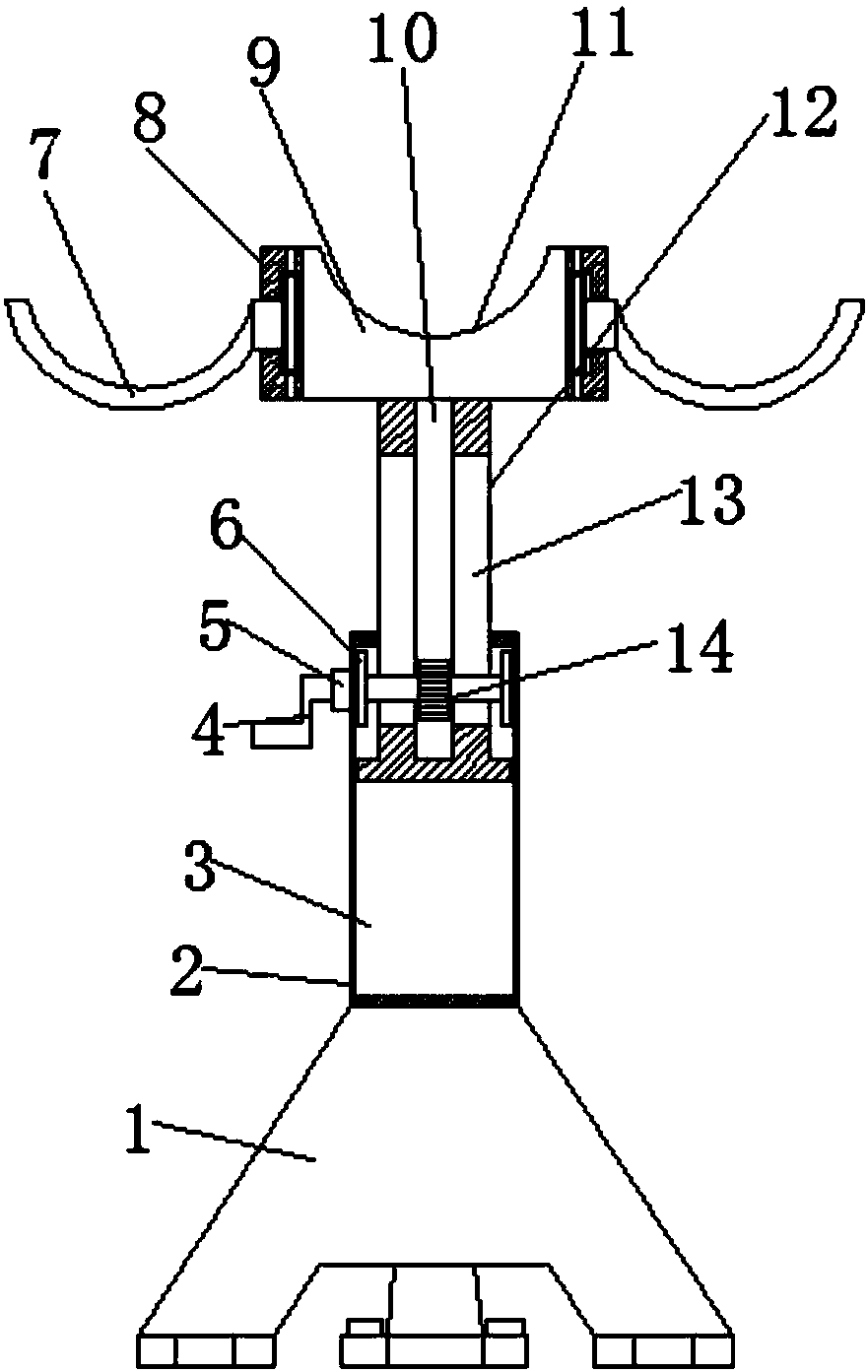
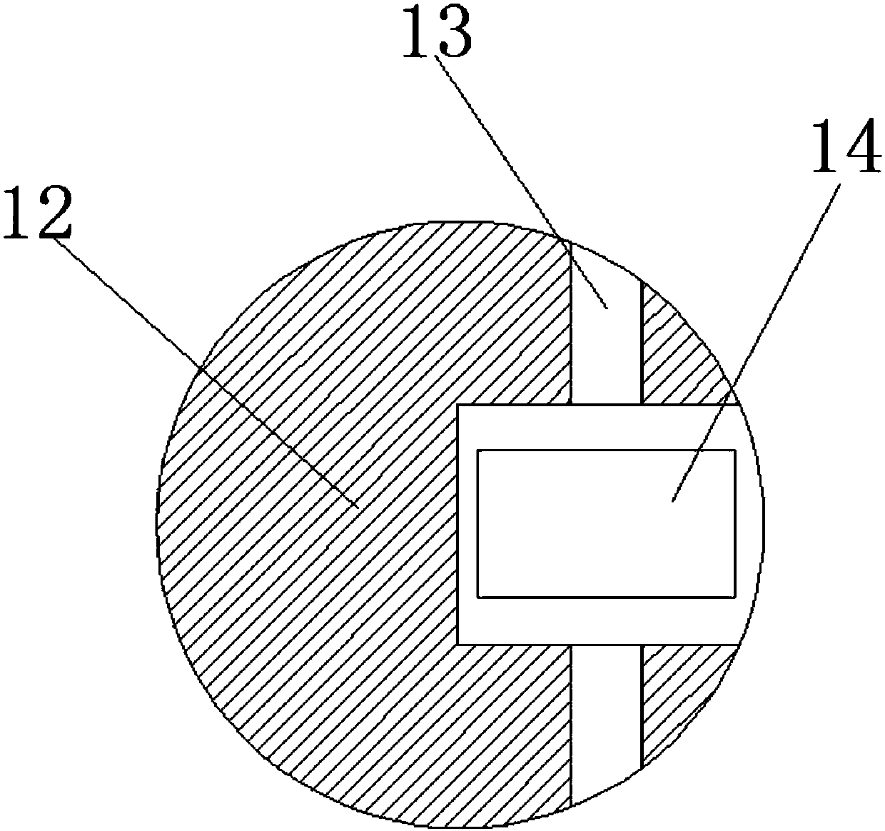
[0017] refer to Figure 1-2 , a glass steel pipe fixing frame, comprising a fixed base 1, the top of the fixed base 1 is provided with a first support rod 2, the inside of the first support rod 2 is provided with a mounting groove 3, and the inside of the mounting groove 3 is provided with a second support rod 12. A connecting block 5 is provided on the upper side of the first support rod 2, and a horizontal rotating shaft 15 is installed inside the connecting block 5. One side of the rotating shaft 15 extends to the outside of the connecting block 5, and a rocker 4 is provided. The other side of the shaft 15 extends to the inside of the mounting groove 3 to be provi...
PUM
 Abstract
Description
Claims
Application Information
 - Generate Ideas
- Intellectual Property
- Life Sciences
- Materials
- Tech Scout
- Unparalleled Data Quality
- Higher Quality Content
- 60% Fewer Hallucinations
Browse by: Latest US Patents, China's latest patents, Technical Efficacy Thesaurus, Application Domain, Technology Topic, Popular Technical Reports.
© 2025 PatSnap. All rights reserved.Legal|Privacy policy|Modern Slavery Act Transparency Statement|Sitemap|About US| Contact US: help@patsnap.com