Sampling device

A technology for sampling devices and sampling rods, applied in the direction of sampling devices, etc., can solve the problems of damage to sampling rods or sampling heads, affect the accuracy requirements of sampling and production, and be difficult to insert into material piles, etc., so as to improve the service life, excellent sampling effect, and structure well-designed effects

Pending Publication Date: 2018-01-19
HUNAN SUNDY SCI & TECH DEV
View PDF7 Cites 6 Cited by
  • Summary
  • Abstract
  • Description
  • Claims
  • Application Information

AI Technical Summary

Problems solved by technology

[0005] (1) After the sampling rod of the existing sampling device is inserted into the stockpile for sampling and pulled out, it is easy to bring out some residual materials that are not required for collection. This is easy to cause ash and coal, which is not environmentally friendly; Sampling with subsequent batches will cause mixed samples, which will seriously affect the accuracy requirements of subsequent sampling and production
However, if a vibration mechanism is installed for vibration, the vibration source will seriously affect the coordination accuracy and service life of the sampling rod itself, the sampling rod driving device, and the sampling rod lifting device, which will not only increase the risk of subsequent operations, but also increase the use cost of the equipment
[0006] (2) When the existing sampling device is lifting and sampling, due to the high density of the material, the position of the sampling rod is prone to misalignment, resulting in inaccurate sampling, and even damage to the sampling rod or sampling head in severe cases
[0007] (3) The structure of the lifting system of the existing sampling device is complicated, and there are a series of problems such as unstable transmission and unbalanced force
[0008] (4) The structure design of the sampling rod of the existing sampling device is not firm, and it is easy to bend and deform due to force overload when inserting and sampling
And part of the sampling head has complex structure, not only easy to take out excess material, but also difficult to insert into the stockpile, affecting the effect of deep sampling

Method used


Image

  • Sampling device
  • Sampling device
  • Sampling device

Examples


Embodiment Construction

[0041] The present invention will be described in further detail below in conjunction with specific embodiments and accompanying drawings.

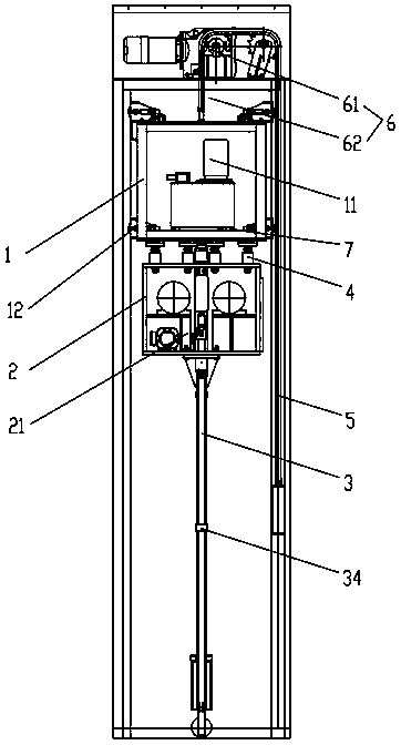
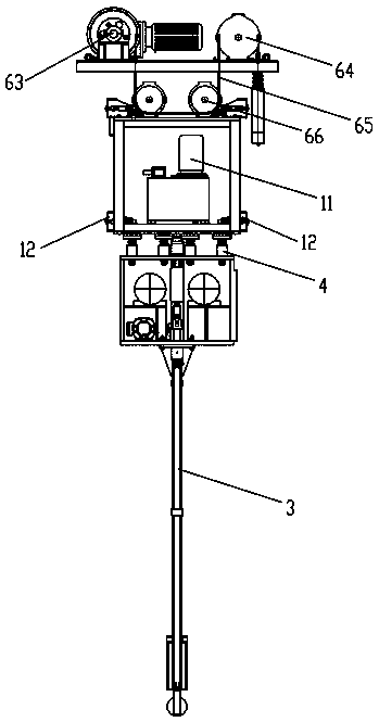
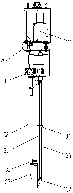
[0042] Such as Figure 1 to Figure 7 As shown, the present invention provides a sampling device, including a guide frame 1, a vibrating frame 2 and a sampling rod assembly 3 arranged up and down, the guide frame 1 is provided with a sampling drive assembly 11, and the sampling drive assembly 11 is installed on the guide frame 1. The upper end of the sampling rod assembly 3 passes through the vibrating frame 2 and is connected with the sampling drive assembly 11 for driving sampling. The vibrating frame 2 is provided with a vibrating assembly 21 for vibrating the sampling rod assembly 3. The guide frame 1 The bottom end is connected to the top end of the vibrating frame 2 through a plurality of vibration-damping connection assemblies 4, so as to form a shock absorber. The specific implementation principle is as follows: when the sampling...


PUM


Abstract

The invention discloses a sampling device. The sampling device comprises a guiding framework, a vibrating framework and a sampling rod component which are arranged up and down, wherein a sampling driving component is arranged in the guiding framework; the upper end of the sampling rod component penetrates through the vibrating framework and then is connected with the sampling driving component soas to drive sampling; a vibrating component is arranged in the vibrating framework and is used for enabling the sampling rod component to generate vibration; and the bottom end of the framework is connected with the top end of the vibrating framework through a plurality of vibration reduction connecting components so as to form buffer vibration reduction. The sampling device disclosed by the invention has the advantages of simple and compact structure, good sampling effect, good vibration reducing effect, long service life and capability of ensuring representativeness and authenticity of a sample.

Description

technical field [0001] The invention mainly relates to the field of sampling equipment for material samples, in particular to a sampling device. Background technique [0002] For the sampling, sample preparation, and testing of material (such as ore, coal) samples, each country has mandatory standards, and the sampling and processing of samples must be carried out in accordance with the standards. The principle of sample sampling, sample preparation, and testing work process is to gradually reduce the particle size and quality of the collected samples without destroying the representativeness of the sample, until it meets the particle size and quality of the sample in the laboratory test ( Weight) accuracy requirements, and then carry out relevant laboratory analysis on the samples that meet the requirements. [0003] For example, taking coal sampling as an example, it is actually a sampling and analysis process. The purpose of coal sampling and sample preparation is to obt...

Claims


Application Information

Patent Timeline
Patent Type & Authority Applications(China)
IPC IPC(8): G01N1/08
Inventor 钟龙任率
Owner HUNAN SUNDY SCI & TECH DEV
Why Eureka
Try Eureka