Overhead transmission line on-line monitoring device based on non-contact power-obtaining system

An overhead transmission line, non-contact technology, used in battery circuit devices, emergency protection circuit devices for limiting overcurrent/overvoltage, circuit devices, etc. Self-heavy, affecting the current carrying capacity of wires, etc., to achieve the effect of reducing the number of vehicles and personnel dispatched, reducing the frequency of replacement and maintenance, and improving safety

Active Publication Date: 2018-01-19
NORTHEAST DIANLI UNIVERSITY
View PDF10 Cites 19 Cited by
  • Summary
  • Abstract
  • Description
  • Claims
  • Application Information

AI Technical Summary

Problems solved by technology

The most commonly used method is the combined energy supply method of solar panels or small wind generators and power batteries, but the panel area is large, and it is obviously affected by the environment and climate, which consumes a lot of manpower for maintenance, and it is difficult to meet the daily power demand; Capacitive voltage division The energy acquisition of the current transformer needs to be directly obtained from the high-voltage bus, the circuit connection is complicated, the maintenance is difficult, and it has an impact on the transmission wire; changes, resulting in an induced current
However, the weight of the current transformer is very large. If it is placed on the wire, the arc length of the wire will be increased. In the case of ice, the heat will be obvious and the galloping will be intensified, which will seriously affect the current carrying capacity of the wire. in the line of the line
In addition, there are some energy-taking methods based on the changes of the above-mentioned methods, but the principles are roughly the same and have great limitations.

Method used


Image

  • Overhead transmission line on-line monitoring device based on non-contact power-obtaining system
  • Overhead transmission line on-line monitoring device based on non-contact power-obtaining system
  • Overhead transmission line on-line monitoring device based on non-contact power-obtaining system

Examples


Embodiment Construction

[0029] The present invention will be described in more detail below in conjunction with the accompanying drawings and specific examples.

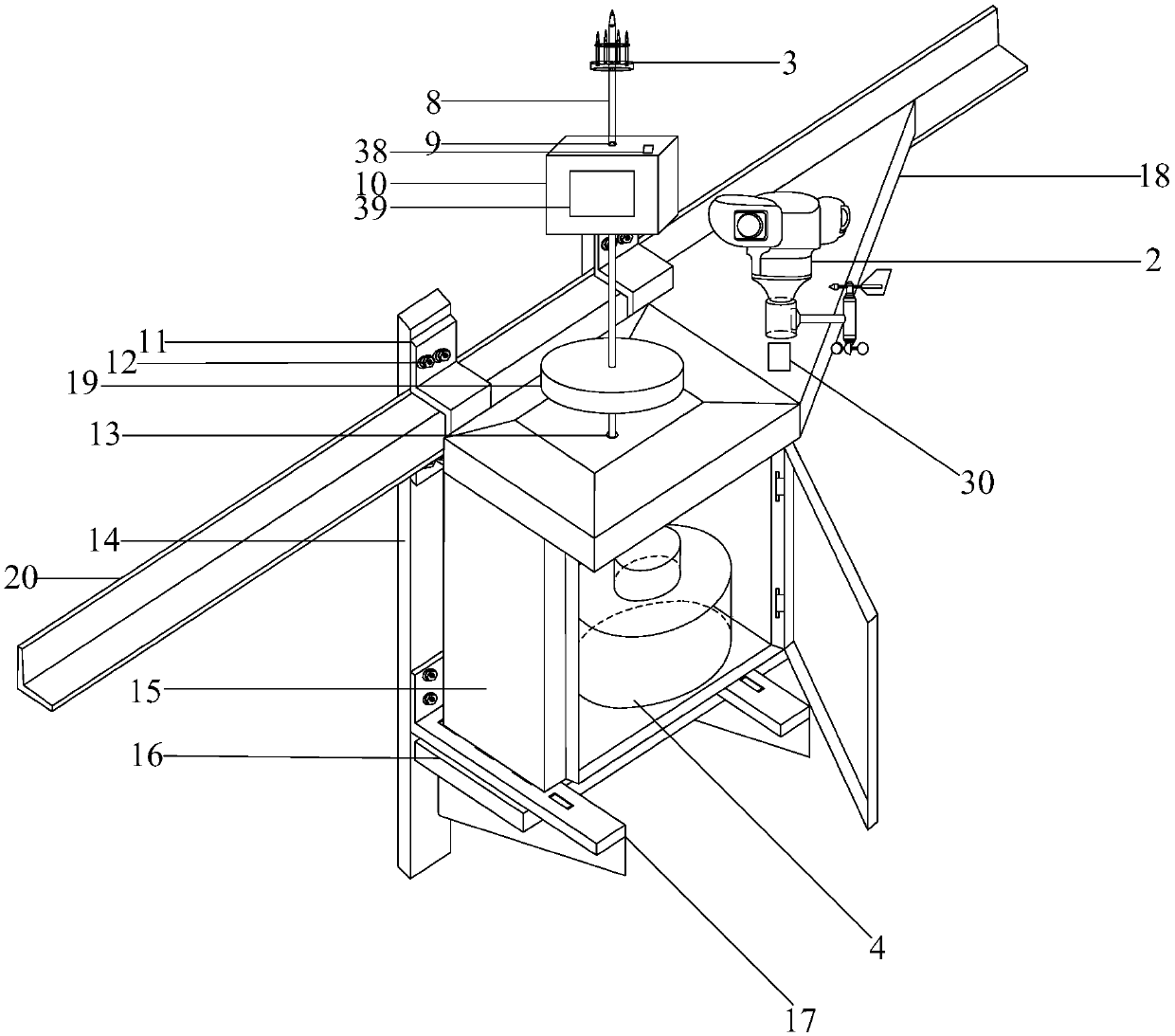
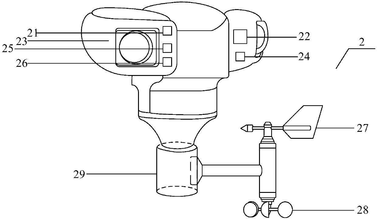
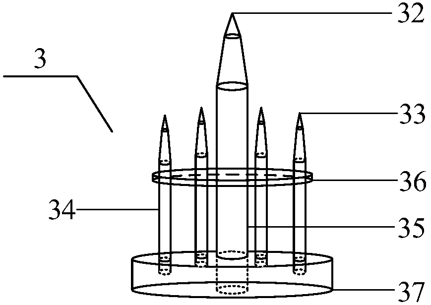
[0030] refer to figure 1 — Figure 10 , an overhead transmission line online monitoring device based on a non-contact power taking system of the present invention, including a mechanical load protection system 1, an online monitoring system 2, an induction energy storage adjustment control system 3, a gap discharge energy taking control system 4, and a sensor Monitoring and analysis system 5, main control system 6, energy supply protection system 7, the online monitoring system 2, induction energy storage adjustment control system 3, gap discharge energy acquisition control system 4, sensor monitoring and analysis system 5, main control system 6, The energy supply protection system 7 is all arranged on the mechanical load protection system.

[0031] refer to figure 1 — Figure 6 , the mechanical bearing protection system 1 includes a hi...


PUM


Abstract

The invention provides an overhead transmission line on-line monitoring device based on a non-contact power-obtaining system. The monitoring device is characterized by including a mechanical bearing protection system, an on-line monitoring system, a sensing energy storage adjusting control system, a gap discharge power-obtaining control system, a sensor monitoring analysis system, a master controlsystem and a power supplying protection system, the on-line monitoring system, the sensing energy storage adjusting control system, the gap discharge power-obtaining control system, the sensor monitoring analysis system, the master control system and the power supplying protection system all being arranged on the mechanical bearing protection system. The monitoring device has the advantages of being reasonable in structure and long in service life, being free from extra connection of a power source, needing battery replacement, being convenient to maintain, having a good effect, etc.

Description

technical field [0001] The invention relates to the technical field of an overhead power transmission line on-line monitoring system and wireless power fetching, in particular to an overhead power transmission line on-line monitoring device based on a non-contact power fetching system. Background technique [0002] UHV transmission lines have large transmission capacity, long distances, and complex terrain and meteorological conditions along the way. As a result, when the battery power supply of online monitoring equipment is insufficient, they cannot be repaired and replaced in time, resulting in interruption of monitoring information and failure to achieve the purpose of real-time monitoring. And when replacing and maintaining, the life safety of live working personnel is caused huge threat. [0003] On-line monitoring and fault diagnosis of transmission lines refers to the measurement, transmission and diagnosis system that is directly installed on the line equipment and ...

Claims


Application Information

Patent Timeline
Patent Type & Authority Applications(China)
IPC IPC(8): G01R31/08H02H7/26H02H9/04H02J7/00H02J13/00
CPCY02E60/00Y04S10/20
Inventor 祝贺王基琛崔晓彤何旭刘阳
Owner NORTHEAST DIANLI UNIVERSITY
Why Eureka
Try Eureka