
Switch circuit and terminal equipment

A technology of switching circuit and voltage dividing circuit, applied in the field of electronics, can solve the problems of high cost and poor flexibility, and achieve the effect of low cost, high cost performance, and improved flexibility and practicability

Inactive Publication Date: 2018-01-19
SHENZHEN WATER WORLD CO LTD
View PDF5 Cites 7 Cited by
  • Summary
  • Abstract
  • Description
  • Claims
  • Application Information

AI Technical Summary

Problems solved by technology

At present, the switching circuit of the control circuit path in the terminal equipment mainly adopts the method of integrated chip, but this method is costly and belongs to centralized control, and the flexibility is poor

Method used


Image

  • Switch circuit and terminal equipment
  • Switch circuit and terminal equipment

Examples


Embodiment Construction

[0019] It should be understood that the specific embodiments described herein are only used to explain the present invention, but not to limit the present invention.

[0020] The embodiments of the present invention will be described in detail below. Examples of the embodiments are shown in the accompanying drawings, wherein the same or similar reference numerals indicate the same or similar elements or elements with the same or similar functions. The embodiments described below with reference to the accompanying drawings are exemplary, and are only used to explain the present invention, and cannot be construed as limiting the present invention.

[0021] Those skilled in the art can understand that, unless specifically stated otherwise, the singular forms "a", "an", "said" and "the" used herein may also include plural forms. It should be further understood that the term "comprising" used in the specification of the present invention refers to the presence of the described features,...


PUM


Abstract

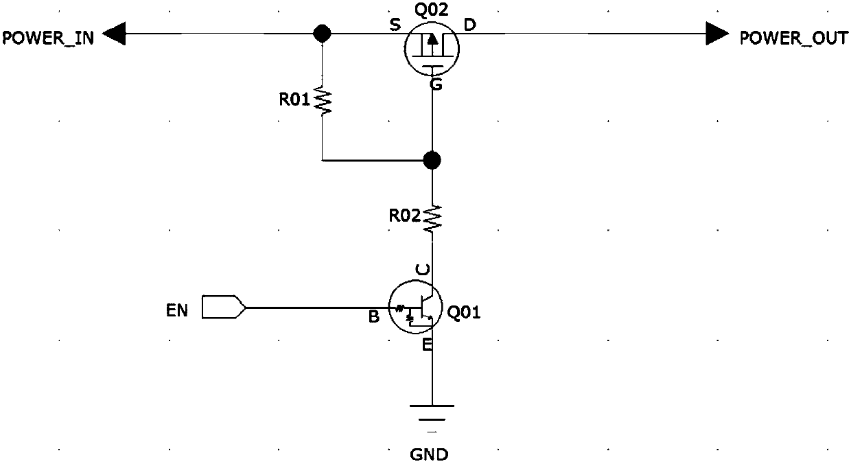
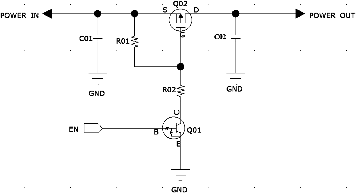
The invention discloses a switch circuit and terminal equipment. The switch circuit comprises a power input end, a power output end, an enable end, a field-effect transistor, a triode and a voltage division circuit, wherein a source electrode of the field-effect transistor is connected with a power path through the power input end, and a drain electrode of the field-effect transistor is connectedwith a load through the power output end; and a base electrode of the triode is connected with a control pin of a main controller through the enable end, a collector electrode of the triode is connected with the source electrode and a grid electrode of the field-effect transistor through the voltage division circuit, and an emitting electrode of the triode is grounded. The switch circuit disclosed by the embodiment of the invention is simple in circuit structure and relatively low in cost, can achieve separate control, has high cost performance, and improves the flexibility and practicability.

Description

Technical field [0001] The present invention relates to the field of electronic technology, in particular to a switch circuit and terminal equipment. Background technique [0002] Reasonable control of power supply plays a key role in system power consumption and product life. At present, the switch circuit of the control circuit path in the terminal equipment mainly adopts an integrated chip method, but this method has a higher cost, is a centralized control, and has poor flexibility. [0003] Therefore, how to reduce the cost of the switching circuit and improve the flexibility is a technical problem that needs to be solved urgently. Summary of the invention [0004] The main purpose of the present invention is to provide a switch circuit and terminal equipment, aiming to reduce the cost of the switch circuit and improve flexibility. [0005] To achieve the above objective, an embodiment of the present invention provides a switch circuit, the switch circuit includes a power input ...

Claims


Application Information

Patent Timeline
Patent Type & Authority Applications(China)
IPC IPC(8): H03K17/567
CPCH03K17/567
Inventor 唐远强王辉耀方杰
Owner SHENZHEN WATER WORLD CO LTD
Learn More