


Quick Research
Generate reliable direction feasibility study reports for your R&D in just a few steps.

Technical Q&A
Discover and master advanced knowledge NOW. Basics, ideas, possibilities, all at once.

Find Solutions
As an expert in R&D theories, this can generate solutions to your technical problems instantly.

Evaluate Feasibility
Analyze your overall solution with one click, know your potential R&D risks in advance.

Monitor Landscape
Get weekly tech updates, stay abreast of the latest tech innovations and key insights.
Battery, battery case and battery case welding method
A welding method and battery case technology, which is applied to battery pack components, circuits, electrical components, etc., can solve the problems of battery safety, poor sealing and heat dissipation, and achieve the effect of high reliability and small gaps
- Summary
- Abstract
- Description
- Claims
- Application Information
AI Technical Summary
Problems solved by technology
Method used
Image

Examples
Embodiment 1
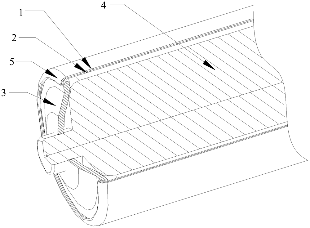
[0044] Please also refer to figure 2 and Figure 4 , Figure 4 is a structural schematic diagram of the first embodiment of the battery case welding method of the present invention, that is figure 2Partial enlarged view of the structure A of the welding part in the embodiment; in this embodiment, the welding edges (215 and 225) on both sides of the welding part of the battery case are parallel to the sides of the battery case, overlapping and closely arranged, and the welding edge 215 of the upper case 210 The top surface of the upper shell is bent at right angles, and the welding edge 225 of the lower shell 220 is a straight edge, which is equivalent to the welding edge 215 of the upper shell 210 enclosing the welding edge 225 of the lower shell 220, and the laser welding lines 202 are welded on both sides. Wavy distribution on the outer side of the overlapping surface.
[0045] Of course, the wavy shape of the laser welding lines 202 is not limited to the straight line ...
Embodiment 2
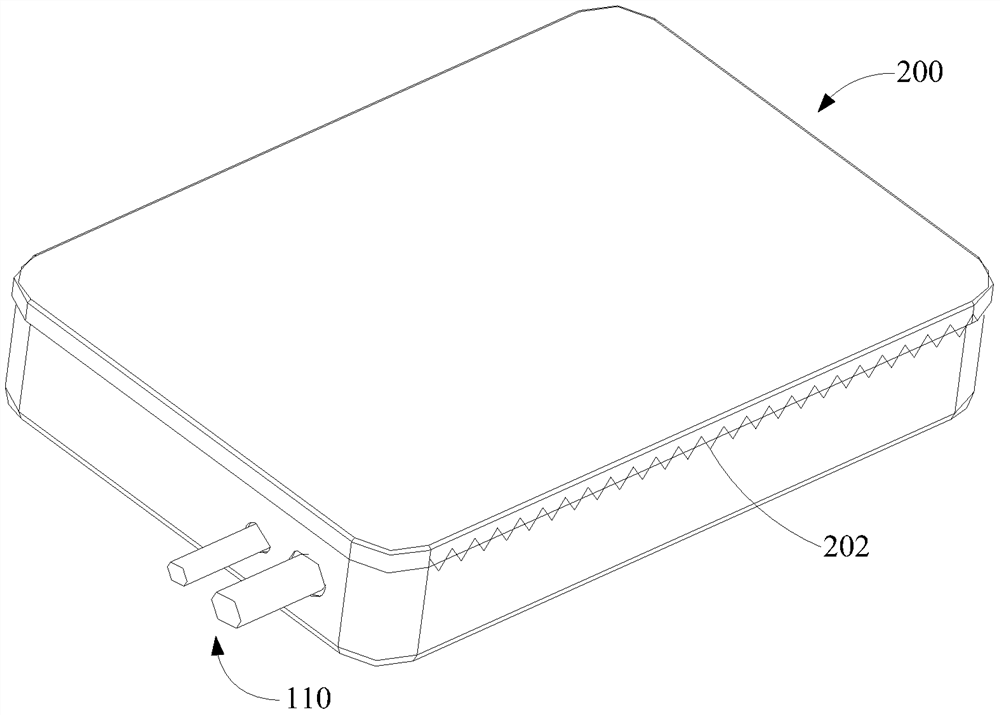
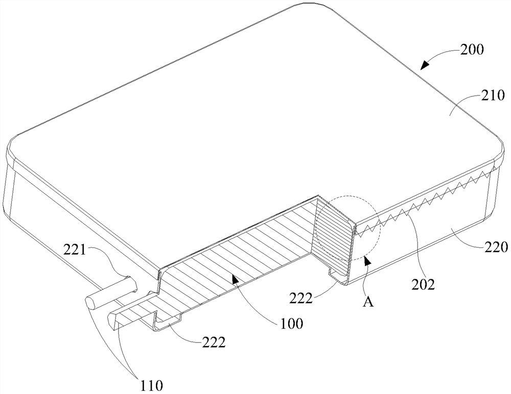
[0050] Please also refer to Figure 6 and Figure 7 , Figure 6 It is a structural schematic diagram of the second embodiment of the battery case welding method of the present invention; Figure 7 yes Figure 6 Partial enlarged view of structure B at the welding site in the embodiment. In this embodiment, the welding edges (215, 225) on both sides of the welding part of the battery case extend outward along the side of the battery case, and the welding edges (215, 225) on both sides are overlapped and arranged closely, and the laser welding lines 202 are on both sides. The outer sides of the overlapping surfaces of the welding edges (215, 225) are distributed in waves.
[0051] Preferably, the welding edges (215, 225) on both sides are bent at right angles to the side of the battery case. Also preferably, the material of the battery case 200 (including the upper case 210 and the lower case 220) is 0.07 mm thick stainless steel, laser The spot diameter of welding is 0.08mm...
Embodiment 3
[0054] see Figure 8 , Figure 8 It is an enlarged schematic diagram of the structure of the welding part of the third embodiment of the battery case welding method of the present invention, in Figure 6 In the embodiment, since the welding edges (215, 225) on both sides are bent at right angles relative to the side of the battery case, the welding edges protrude outward relative to the case, which will increase the peripheral size of the battery case. Therefore, this embodiment as Figure 6 A modification of the embodiment, in Figure 6 On the basis of the embodiments, the welded overlapping faces are bent in a direction parallel to the side of the battery case, so as to reduce the peripheral size of the battery case and make the battery case more beautiful as a whole.
PUM
 Abstract
Description
Claims
Application Information
 - R&D Engineer
- R&D Manager
- IP Professional
- Industry Leading Data Capabilities
- Powerful AI technology
- Patent DNA Extraction
Browse by: Latest US Patents, China's latest patents, Technical Efficacy Thesaurus, Application Domain, Technology Topic, Popular Technical Reports.
© 2024 PatSnap. All rights reserved.Legal|Privacy policy|Modern Slavery Act Transparency Statement|Sitemap|About US| Contact US: help@patsnap.com