
Device for coal powder injection of blast furnace

A blast furnace and pulverized coal technology, which is applied to blast furnaces, blast furnace details, blast furnace parts, etc., can solve problems such as pulverized coal injection and pulsation, and achieve the effects of uniform pulverized coal transportation, improved combustion rate, and uniform time.

Active Publication Date: 2018-01-23
通化钢铁股份有限公司
View PDF2 Cites 5 Cited by
  • Summary
  • Abstract
  • Description
  • Claims
  • Application Information

AI Technical Summary

Problems solved by technology

[0004] The pulverized coal injection pulsation phenomenon in the lower coal injection mode in the prior art is serious

Method used


Image

  • Device for coal powder injection of blast furnace
  • Device for coal powder injection of blast furnace
  • Device for coal powder injection of blast furnace

Examples


Embodiment 1

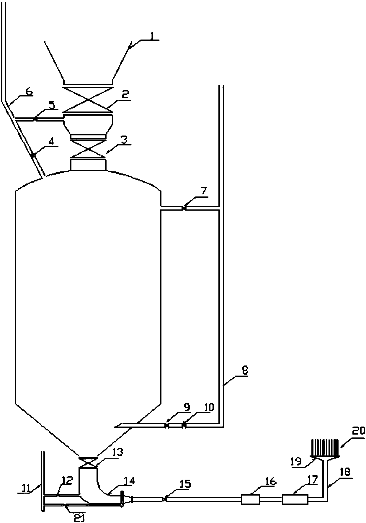
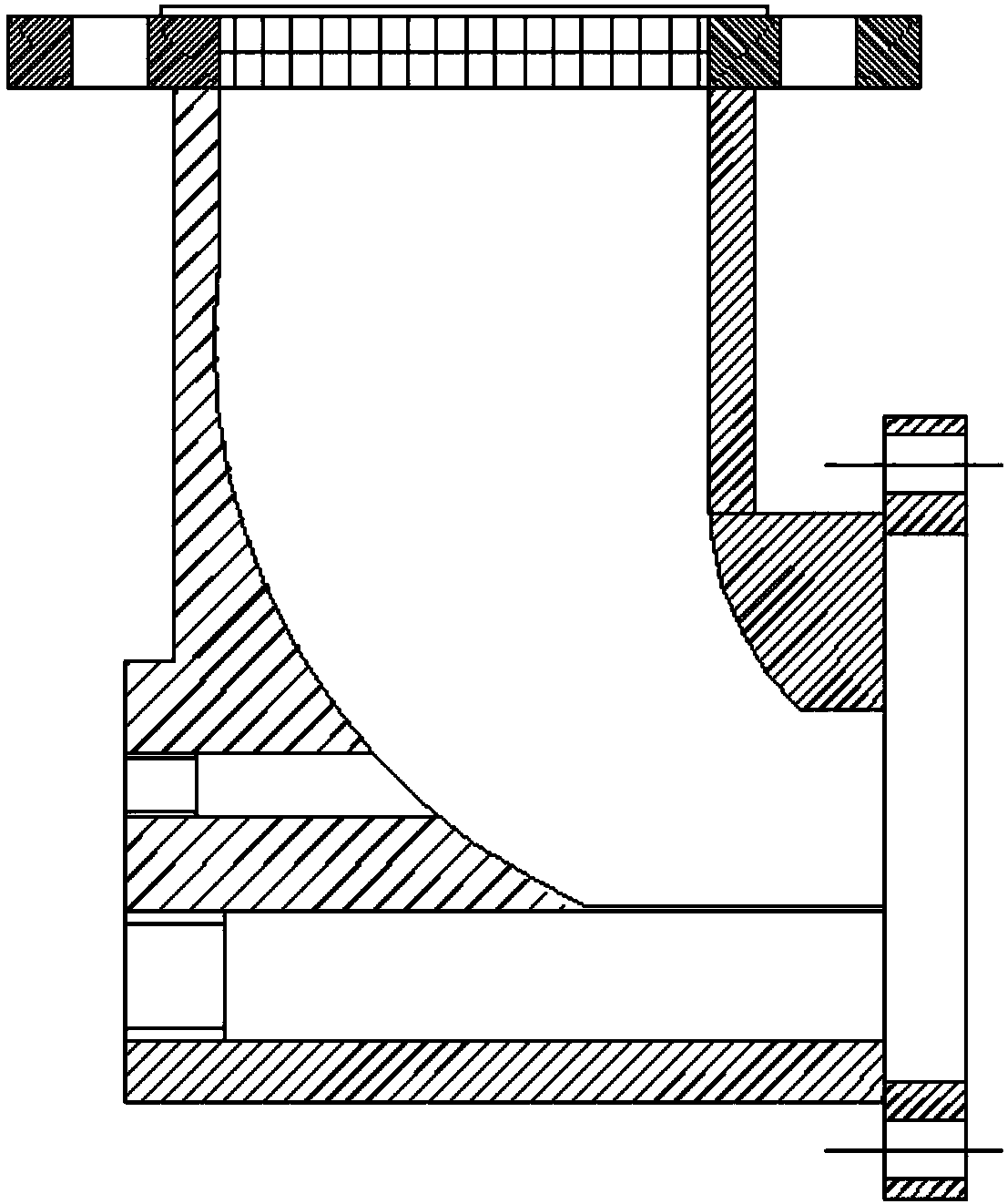
[0037] figure 1 It is a schematic structural diagram of a device for injecting pulverized coal into a blast furnace provided in an embodiment of the present application. Such as figure 1 As shown, the blast furnace is connected with a blow tank, and the device includes:

[0038] The first nitrogen pipeline 8 is arranged at a first position on the bottom of the spray tank.

[0039]Further, the conduit of the first nitrogen pipeline 8 at the inner part of the spray tank has a chamfered surface, and the chamfered surface faces the top of the spray tank.

[0040] Specifically, the first nitrogen pipeline 8 is arranged at a first position on the bottom of the spray tank, and the pipeline of the first nitrogen pipeline 8 is in the shape of a right angle. The first regulating valve 10 and the pneumatic ball valve 9 are provided, and the pressure of the pipeline can be adjusted through the charging valve 7, and the first nitrogen pipeline 8 goes deep into the inner part of the blow...

Embodiment 2

[0061] The operating principle of a kind of blast furnace pulverized coal injection device of the present invention is described in detail below, specifically as follows:

[0062] The process flow of the device includes: normally open fluidized blowing tank → first mixer with filter → second mixer for supplementing gas in proportion → dual-purpose filter for gas back blowing and manual cleaning → high precision Distributorbranch pipe of equal length→spray gun adjusted in real time.

[0063] When the blast furnace starts coal injection, adjust the opening degree of the first regulating valve 10 in time, and keep the pneumatic ball valve 9 in a normally open state through adjustment, and the gas continuously enters the injection tank as the injection process progresses. Due to the difference in the amount of coal injected into the blast furnace, the opening of the pneumatic ball valve 9 in the injection tank will be different, and the automatic adjustment can be realized throug...


PUM


Abstract

The invention discloses a device for coal powder injection of a blast furnace, and relates to the technical field of blast furnace ironmaking. The device comprises a first nitrogen pipeline, a secondnitrogen pipeline, a first adjusting valve and a pneumatic ball valve, wherein the first nitrogen pipeline is arranged on a first position of the bottom of an injection tank, the second nitrogen pipeline is arranged on a second position of the bottom of the injection tank, and the first position is different from the second position; and the first adjusting valve is arranged on the first nitrogenpipeline, the first adjusting valve adjusts the gas flow rate of the first nitrogen pipeline to the injection tank, the pneumatic ball valve is arranged on the first nitrogen pipeline, the pneumatic ball valve adjusts the gas flow rate of the first nitrogen pipeline to the injection tank. Through the device for coal powder injection of the blast furnace, the technical problem that a pulsation phenomenon of coal powder injection is severe through a lower coal producing and injection mode is solved, and the technical effects that the pulsation phenomenon of coal powder injection is eliminated, so that coal powder conveying is evener, the blast furnace operates stably and smoothly, and the cost is reduced are achieved.

Description

technical field [0001] The invention relates to the technical field of blast furnace ironmaking, in particular to a device for injecting pulverized coal into a blast furnace. Background technique [0002] Blast furnace pulverized coal injection technology is to use cheap non-coking coal to partially replace expensive metallurgical coke, and it is conducive to the intensified smelting of blast furnaces and the smooth operation of furnace conditions, which can greatly improve the technical and economic indicators of blast furnaces, and has significant economic benefits. It can also ease the demand for coke, reduce coke consumption, and reduce environmental pollution caused by coking production. [0003] However, in the process of realizing the technical solution of the invention in the embodiment of the present application, the inventor of the present application found that the above-mentioned technology has at least the following technical problems: [0004] The pulverized c...

Claims


Application Information

Patent Timeline
Patent Type & Authority Applications(China)
IPC IPC(8): C21B7/00C21B5/00
Inventor 张联兵
Owner 通化钢铁股份有限公司
Learn More