
Electroplating anode device and chromium plating method

An anode device and anode technology, applied in the direction of the electrode, etc., can solve the problems of increased electroplating operation and safety risks, poor dispersibility of chromium plating solution, uneven thickness of coating deposition, etc., to achieve uniform appearance color, smooth and compact appearance, tooling The design is simple and practical

Active Publication Date: 2018-01-23
LANDING GEAR ADVANCED MFG
View PDF7 Cites 2 Cited by
  • Summary
  • Abstract
  • Description
  • Claims
  • Application Information

AI Technical Summary

Problems solved by technology

[0002] With the development of industry and the increase in the service life requirements of products, for large structural workpieces, electroplating is no longer the "trunk" part, but the electroplating of key parts such as "branches", which is common in complex workpiece arms, ears, etc. Fork and other key parts, due to the poor dispersibility of the chromium plating solution, the electroplating part needs to be parallel to the anode, and some of the electroplating parts are not parallel to the general anode in the electroplating tank, and are relatively scattered. In the electroplating process of such structures, the lines of force are difficult to concentrate, and the current density Uneven dispersion, resulting in uneven deposition thickness of the coating after electroplating, and low electroplating efficiency
[0003] If the workpiece is deliberately rotated at a certain angle so that the electroplating part is parallel to the outer anode, it will be difficult to enter the tank due to the influence of other parts and the size of the electroplating tank, and increase the electroplating operation and safety risks; therefore, it is necessary to design a simple and practical process in the electroplating process device to obtain a uniform and dense qualified coating to achieve its electroplating process

Method used

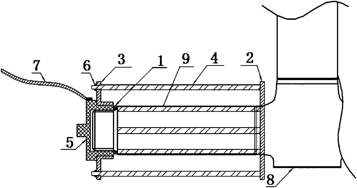
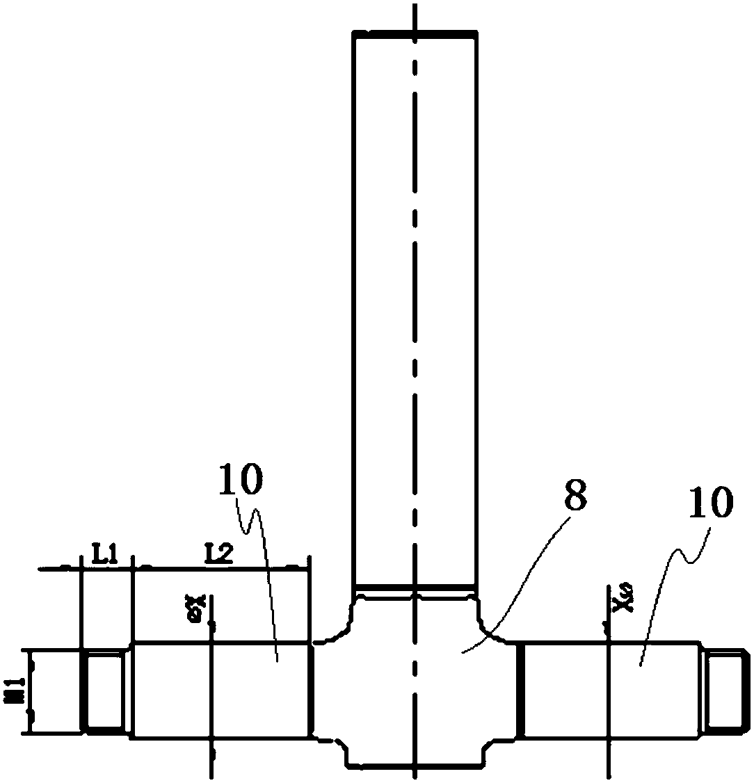
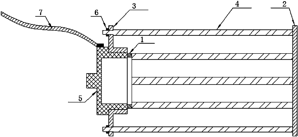

Image

  • Electroplating anode device and chromium plating method
  • Electroplating anode device and chromium plating method
  • Electroplating anode device and chromium plating method

Examples


Embodiment Construction

[0038] The present invention will be described in detail below with reference to the accompanying drawings and examples. It should be noted that, in the case of no conflict, the embodiments of the present invention and the features in the embodiments can be combined with each other. For the convenience of description, if the words "up", "down", "left" and "right" appear in the following, it only means that the directions of up, down, left and right are consistent with the drawings themselves, and do not limit the structure.

[0039] A kind of cage structure electroplating anode device, such as figure 1 and 3 As shown, the designed device is not affected by the structure and position of the chrome-plated surface. A plurality of anodes evenly distributed on the chrome-plated circumference are designed as a special cage-shaped anode through the combination of the support plate and the anode opening ring, and the anode is fixed by converting the sleeve. In the parts, the electro...


PUM


Abstract

The invention discloses an electroplating anode device and a chromium plating method. The electroplating anode device comprises multiple anode rods. The multiple anode rods form a cage-shaped structure through supporting of a supporting structure. The cage-shaped structure is used for being arranged on the outer side of a chromium plating area on the outer circle of a workpiece in a sleeving manner. A clearance exists between the anode rods and the outer circle of the workpiece. A cathode gasket is arranged between the cage-shaped structure and the end portion of the outer circle of the workpiece. The anode rods are electrically connected with an anode. The workpiece is electrically connected with a cathode. The anode device is simple in structure, cage-shaped anode and workpiece hanging and electric conduction are integrated, in addition, installation is convenient and fast, practicability is high, and the chromium plating effect is good.

Description

technical field [0001] The invention relates to an electroplating anode device and a chrome plating method, belonging to the field of special process processing methods. Background technique [0002] With the development of industry and the increase in the service life requirements of products, for large structural workpieces, electroplating is no longer the "trunk" part, but the electroplating of key parts such as "branches", which is common in complex workpiece arms, ears, etc. Fork and other key parts, due to the poor dispersibility of the chromium plating solution, the electroplating part needs to be parallel to the anode, and some of the electroplating parts are not parallel to the general anode in the electroplating tank, and are relatively scattered. In the electroplating process of such structures, the lines of force are difficult to concentrate, and the current density Uneven dispersion will lead to uneven deposition thickness of the coating after electroplating, an...

Claims


Application Information

Patent Timeline
IPC IPC(8): C25D17/12C25D3/04
Inventor 杨鹏宗洋洋李志栋谭子豪吴红军张升李博
Owner LANDING GEAR ADVANCED MFG
Learn More