Sludge treatment system and sludge treatment method

A sewage treatment system and sludge treatment technology, used in sludge treatment, biological sludge treatment, water/sludge/sewage treatment, etc.

Inactive Publication Date: 2014-09-10
王胜初
View PDF5 Cites 16 Cited by
  • Summary
  • Abstract
  • Description
  • Claims
  • Application Information

AI Technical Summary

Problems solved by technology

[0005] The sludge disposal methods currently used in the field of sludge treatment can basically only achieve one or two of the problems of sludge recycling, harmlessness, reduction, and stabilization that are stipulated and required by the state. Can meet all four criteria

Method used


Image

  • Sludge treatment system and sludge treatment method
  • Sludge treatment system and sludge treatment method

Examples


Embodiment 1

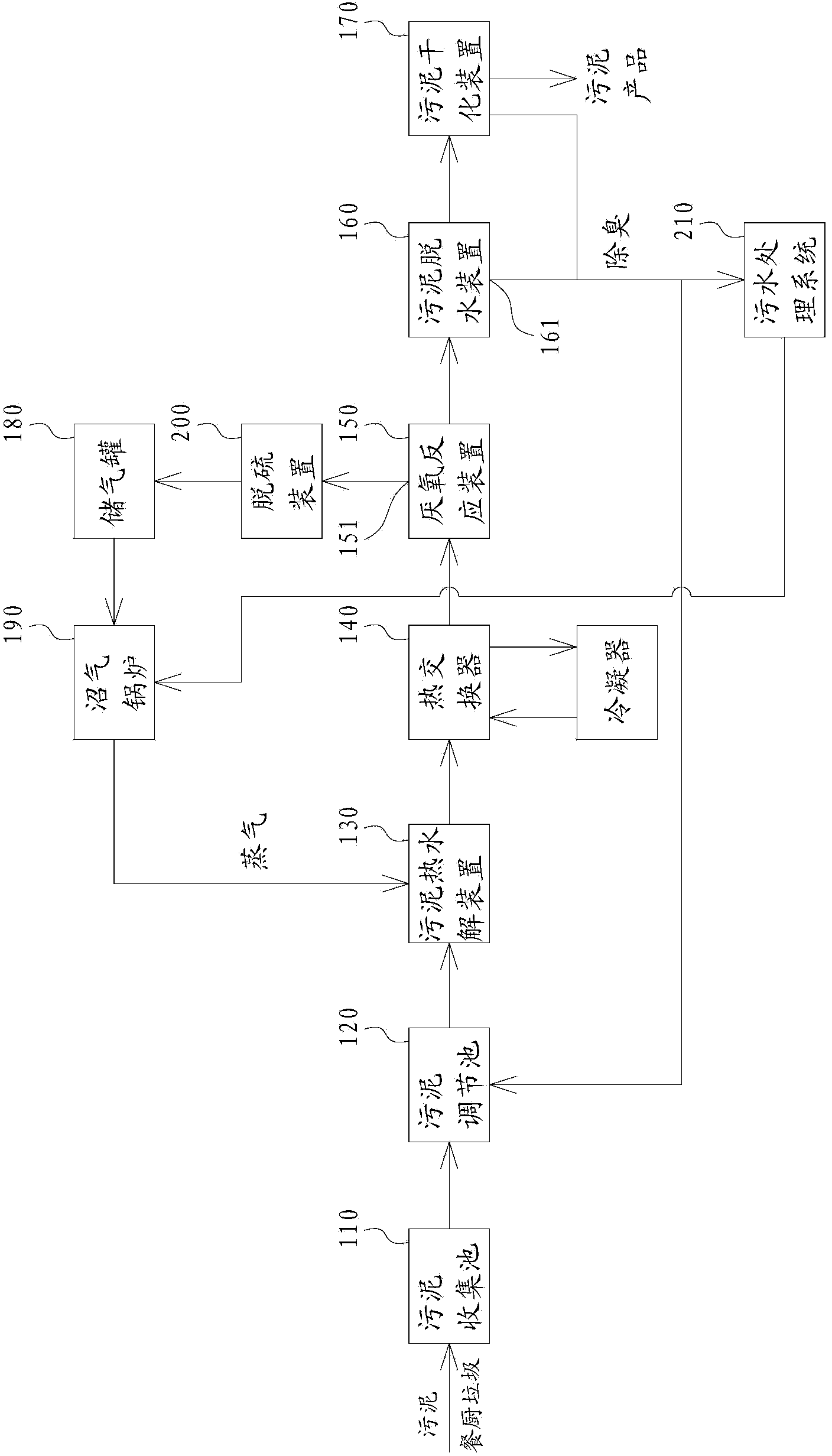
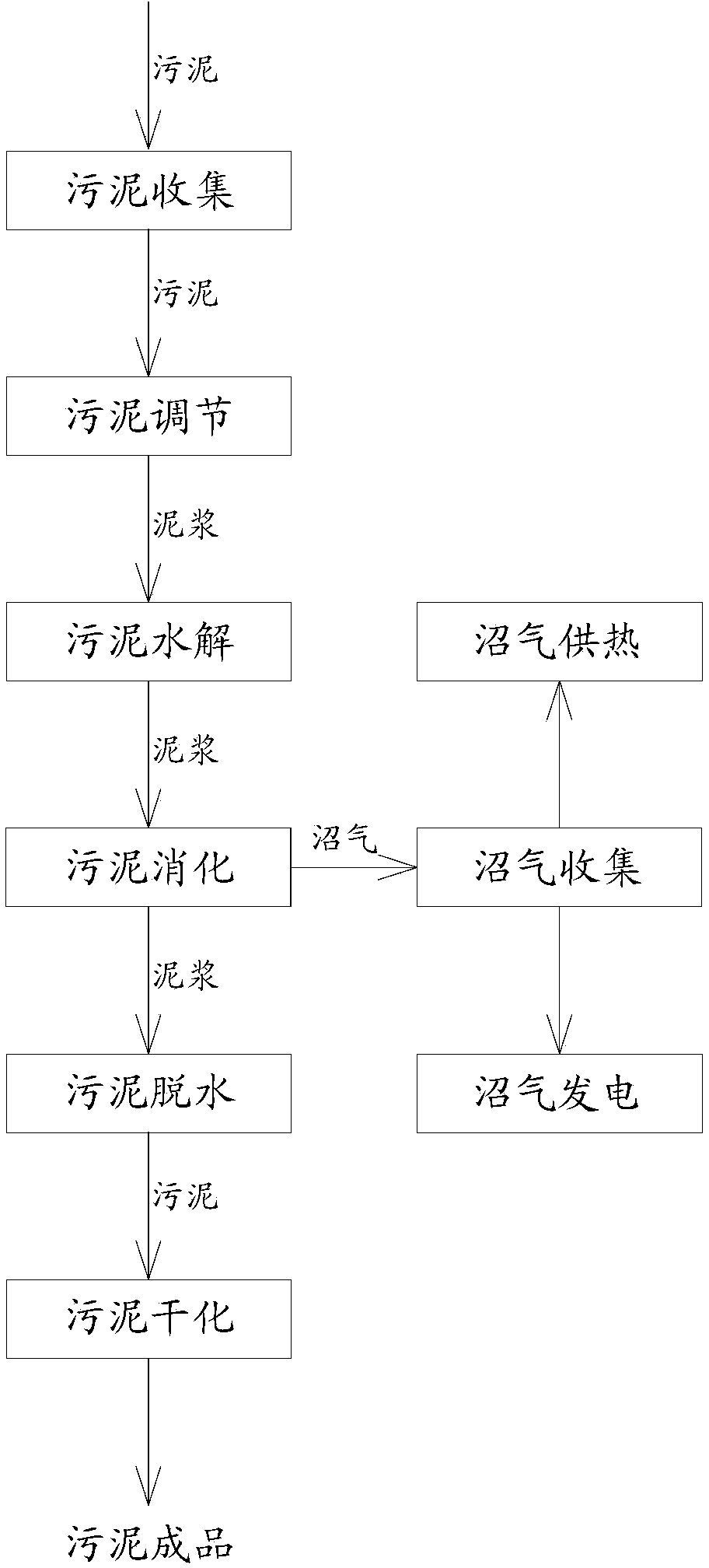
[0041] Sludge from urban sewage plants and kitchen waste are mixed at a ratio of 4:1 in the sludge collection tank 110, and then filtered through the filter grid and then transported to the sludge adjustment tank 120, where the water content of the sludge is adjusted to 80%. Then the sludge is transported to a closed sludge hydrolysis tank with a screw pump, and the high-pressure steam is directly passed into the sludge hydrolysis tank to heat the sludge, and the sludge is heated to 135°C and kept for 2 hours for hydrolysis. The hydrolyzed sludge was transported to the heat exchanger 140 by a screw pump to cool down to 45°C, and then transported to a closed anaerobic reaction tank for anaerobic digestion for 17 days. The biogas produced in the anaerobic digestion process is desulfurized by the sulfur device 200 and sent to the gas storage tank 180 for storage. The digested sludge produced after anaerobic digestion is dehydrated and dried by a plate and frame mud compactor and ...

Embodiment 2

[0043] Industrial wastewater sludge and kitchen waste are mixed at a ratio of 5:1 in the sludge collection tank 110, and then filtered through the filter grid and then transported to the sludge adjustment tank 120, where water is added to adjust the water content of the sludge to 85%. The sludge is transported to a closed sludge hydrolysis tank by a screw pump, and the high-pressure steam is directly passed into the sludge hydrolysis tank to heat the sludge, and the sludge is heated to 133°C and kept for 3 hours for hydrolysis. The hydrolyzed sludge is transported to the heat exchanger 140 by a screw pump to cool down to 45° C., and then transported to a closed anaerobic reaction tank for anaerobic digestion for 16 days. The biogas produced in the anaerobic digestion process is desulfurized by the sulfur device 200 and sent to the gas storage tank 180 for storage. The digested sludge produced after anaerobic digestion is dehydrated and dried by a plate and frame mud compactor ...

Embodiment 3

[0045] Industrial wastewater sludge, urban sewage plant sludge and kitchen waste are mixed in the sludge collection tank 110 at a ratio of 2:2:1, and then filtered through the filter grid and then sent to the sludge adjustment tank 120, where the sludge is adjusted to the sludge level by adding water. The water content of the sludge is 90%, and then the sludge is transported to the closed sludge hydrolysis tank by the screw pump, and the high-pressure steam is directly passed into the sludge hydrolysis tank to heat the sludge, and it is heated to 137°C for 4 hours. hydrolysis. The hydrolyzed sludge is transported to the heat exchanger 140 by a screw pump and cooled to 45° C., and then transported to a closed anaerobic reaction tank for anaerobic digestion for 18 days. The biogas produced in the anaerobic digestion process is desulfurized by the sulfur device 200 and sent to the gas storage tank 180 for storage. The digested sludge produced after anaerobic digestion is dehydra...


PUM


Abstract

The invention discloses a sludge treatment system, comprising a sludge collecting tank, a sludge regulating pool, a sludge thermal hydrolysis device, a heat exchanger, an anaerobic reaction device, a sludge dewatering device and a sludge drying device, which are sequentially connected. The sludge treatment system also comprises a gas storage tank and a biogas boiler, wherein the input end of the gas storage tank is connected with the exhaust end of the anaerobic reaction device; the fuel input end of the biogas boiler is connected with the output end of the gas storage tank; the output end of the biogas boiler is connected with the sludge thermal hydrolysis device; the discharge end of the sludge dewatering device is connected with the input end of the sludge regulating pool. The invention also discloses a sludge treatment method. The sludge treatment method comprises the following steps: 1) collecting a sludge material and diluting by water; 2) hydrolyzing the diluted sludge material at high temperature; 3) carrying out anaerobic digestion on the sludge subjected to thermal hydrolysis to obtain biogas and digested sludge; 4) collecting the biogas; 5) dewatering and drying the digested sludge to obtain a sludge product. Reclamation, harmlessness, minimization and stabilization of sludge treatment are achieved by the steps and method.

Description

technical field [0001] The invention relates to the field of solid waste treatment, in particular to a sludge treatment system and a sludge treatment method. Background technique [0002] At present, the mainstream sludge treatment technology routes at home and abroad are roughly divided into five types: 1. Anaerobic sludge digestion method, 2. Sludge aerobic fermentation + land use method, 3. Dry incineration + landfill / building materials auxiliary method, 4. Sludge cement kiln collaborative incineration method, 5. Sludge dehydration landfill method. According to the research and analysis of China Water Network, only about 10% of the limited amount of sludge that enters the treatment process nationwide is recycled to the land after aerobic fermentation treatment, another 20% is used for sanitary landfill, and a small amount is used for landfill. Incineration, building materials utilization, etc. are disposed of, and the remaining 70% are just transported out at will, simpl...

Claims


Application Information

Patent Timeline
Patent Type & Authority Applications(China)
IPC IPC(8): C02F11/00C02F11/04C02F11/10C02F11/12
CPCY02E50/343Y02E50/30
Inventor 王胜初
Owner 王胜初
Why Eureka
Try Eureka