W flame boiler of turbulent burner with inner direct flow and outer turbulent flow ammonia spraying device

A technology of swirl burner and pulverized coal burner, which is applied in the field of NOx emission reduction of swirl burner W flame boiler and W flame boiler. degree, the effect of widening the temperature window

Active Publication Date: 2018-01-09
HARBIN INST OF TECH
View PDF9 Cites 12 Cited by
  • Summary
  • Abstract
  • Description
  • Claims
  • Application Information

AI Technical Summary

Problems solved by technology

[0004] The present invention is to solve existing swirl burner W flame boiler to exist NO x To solve the problems of high emissions and l

Method used


Image

  • W flame boiler of turbulent burner with inner direct flow and outer turbulent flow ammonia spraying device
  • W flame boiler of turbulent burner with inner direct flow and outer turbulent flow ammonia spraying device

Examples


specific Embodiment approach 1

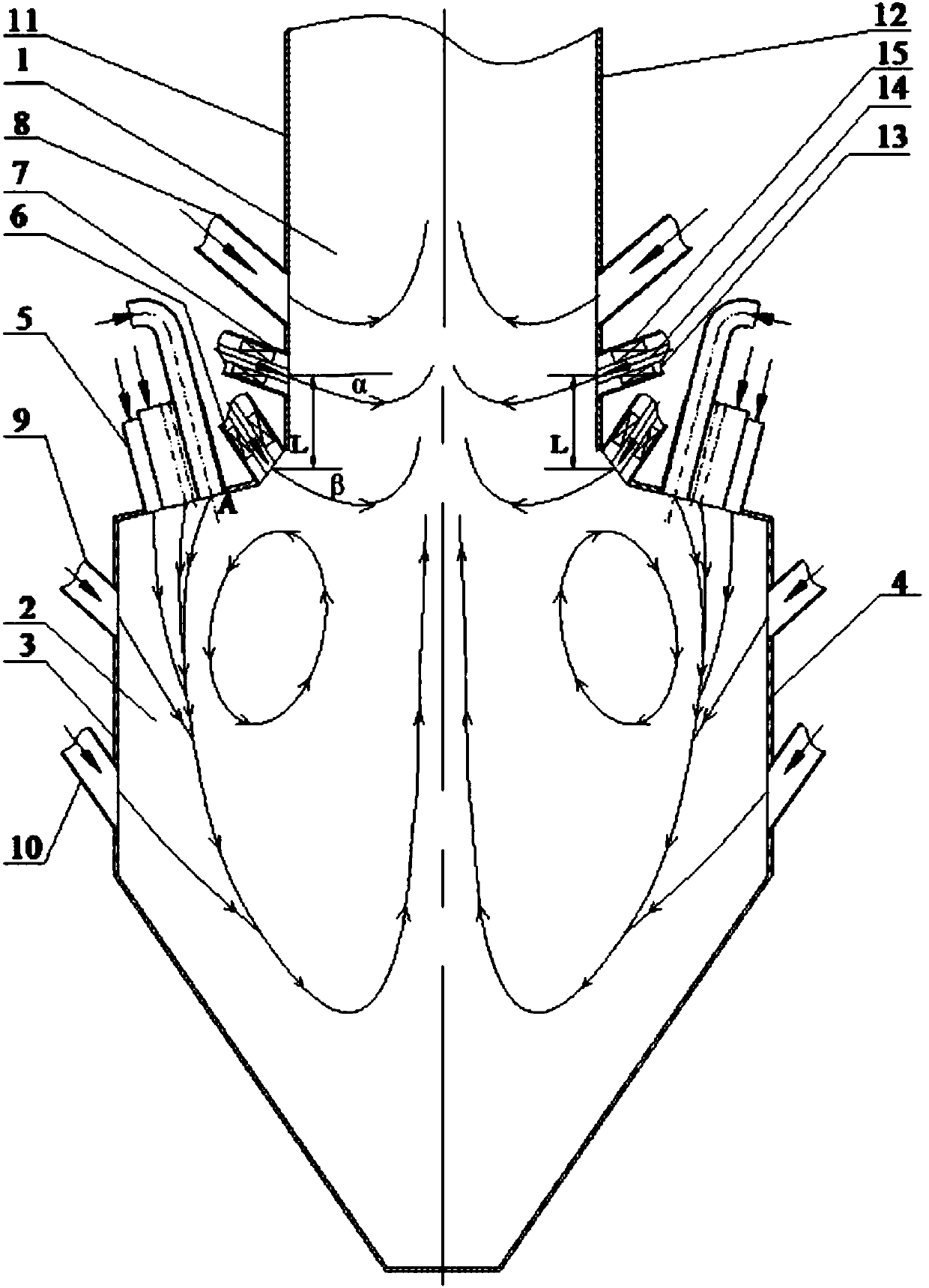
[0026] Specific implementation mode one: as Figure 1~2 As shown, the swirl burner W flame boiler with the inner straight outer swirl ammonia injection device in this embodiment includes an upper furnace 1, a lower furnace 2, a front furnace arch 3, a rear furnace arch 4 and a plurality of offset swirl burners. Stream pulverized coal burner 5, a plurality of offset swirl pulverized coal burners 5 are evenly and symmetrically arranged on the front furnace arch 3 and the rear furnace arch 4, and the W flame boiler also includes a plurality of primary ammonia injection devices 6, A plurality of secondary ammonia injection devices 7, a plurality of burn-off air nozzles 8, a plurality of exhaust air nozzles 9 and a plurality of classified air nozzles 10; On the side wall of the rear furnace arch 4, the first-stage ammonia injection device 6 and the second-stage ammonia injection device 7 are symmetrically and evenly arranged on the front wall 11 and the rear wall 12 of the upper fu...

specific Embodiment approach 2

[0027] Specific implementation mode two: as figure 1 As shown, in this embodiment, the first-stage ammonia injection device 6 and the second-stage ammonia injection device 7 are both arranged downwardly and swing up and down. Such setting is used to change the angle of airflow incidence. Other components and connections are the same as those in the first embodiment.

specific Embodiment approach 3

[0028] Specific implementation mode three: as figure 1 As shown, the angle α formed between the centerline of the first-stage ammonia injection device 6 and the horizontal plane in this embodiment ranges from 30° to 60°. This design is used to change the angle of wind inflow. Other compositions and connections are the same as those in Embodiment 1 or 2.


PUM

PropertyMeasurementUnit
Angleaaaaaaaaaa
Angleaaaaaaaaaa

Abstract

The invention provides a W flame boiler of a turbulent burner with an inner direct flow and outer turbulent flow ammonia spraying device and relates to the W flame boiler. The W flame boiler solves the problems that an existing W flame boiler of the turbulent burner is high in NOx discharge amount and low in denitrifying efficiency. The center of a first stage ammonia spraying device is placed atthe upper edge of a front furnace arch or a back furnace arch, the distance L from the center line of a second stage ammonia spraying device to the upper edge of the front furnace arch or the back furnace arch is 1-2m, the center of the first stage ammonia spraying device is located in a same horizontal plane, and the center of the second stage ammonia spraying device is located on a same horizontal plane; the first stage ammonia spraying device and the second stage ammonia spraying device comprise inner tubes, outer rubes and a plurality of turbulent blades, the inner tubes and the outer tubes are arranged coaxially, the plurality of turbulent blades are uniformly distributed between the inner tubes and the outer tubes, the inner tubes are direct flow nozzles, and the plurality of turbulent blades arranged between the outer tubes and the inner tubes are turbulent nozzles which form the ammonia spraying device with an inner direct flow and an outer turbulent flow. The W flame boiler provided by the invention belongs to the technical field of NOx emission reduction.

Description

technical field [0001] The invention relates to a W-flame boiler, in particular to a W-flame boiler with a swirl burner arranged with two-stage angle-adjustable inner-straight-outer swirl ammonia injection devices in the high-temperature reduction zone of the upper furnace, which belongs to the W-flame boiler NO x Emission reduction technology field. Background technique [0002] NO x It is toxic to animals and humans, is one of the main substances that form acid rain, is also an important substance that forms photochemical smog in the atmosphere and an important factor that destroys the atmospheric ozone layer. NO emissions from coal-fired power plant boilers x Is one of the main sources of air pollution, control NO x Emissions have become one of the global concerns. The W flame boiler with the swirl burner has a low level of combustion classification in the furnace. At the same time, the secondary air of the burner wraps the primary air, and the pulverized coal has str...

Claims


Application Information

Patent Timeline
IPC IPC(8): F23J15/02F23C7/02B01D53/79B01D53/56
Inventor 陈智超王青祥王炳楠曾令艳李争起杨秀超
Owner HARBIN INST OF TECH
Why Eureka
Try Eureka