Eureka AIR delivers breakthrough ideas for toughest innovation challenges, trusted by R&D personnel around the world.

Scriber booster

A marking machine and booster technology, applied in roads, buildings, road repairs, etc., can solve the problems of inconvenient transfer and use on construction sites, unstable marking construction quality, and complex structural layout, etc., to achieve simple structure, Ease of control and enhanced comfort

Pending Publication Date: 2018-01-23
WELL ROAD MACHINERY CO LTD
View PDF12 Cites 0 Cited by
  • Summary
  • Abstract
  • Description
  • Claims
  • Application Information

AI Technical Summary

Problems solved by technology

[0003] Most of the current marking machines are operated by the operator holding the machine forward or backward together with the machine. Since the marking construction is generally outdoor long-distance construction, the operator's long-term hand-held machine work is likely to cause damage to the legs and hands. And the eyes are extremely tired, and the tired working state will also cause the instability of the marking construction quality, and the use of the booster can provide stable power for the marking machine, ensure the marking quality and speed, and reduce the labor intensity of the operator
[0004] The traditional booster uses the engine to connect the continuously variable transmission through the belt drive, and the continuously variable transmission moves the booster through the chain drive. This structure layout is complicated, the power loss is large, and the equipment is bulky, which is not convenient for transportation and use on the construction site.

Method used


Image

  • Scriber booster
  • Scriber booster
  • Scriber booster

Examples


Embodiment Construction

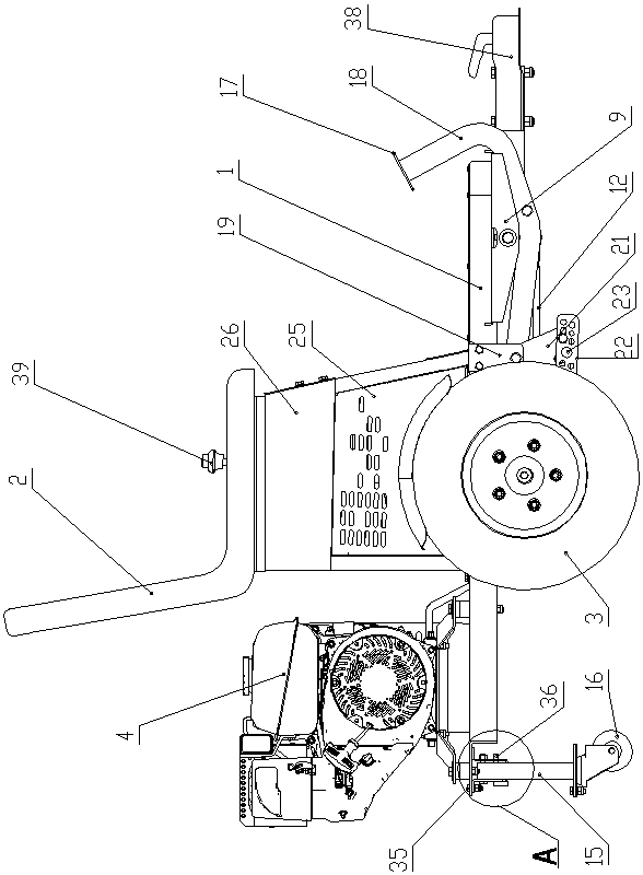
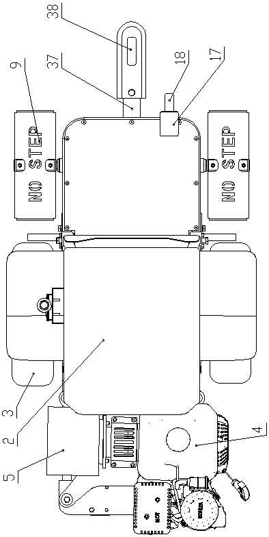
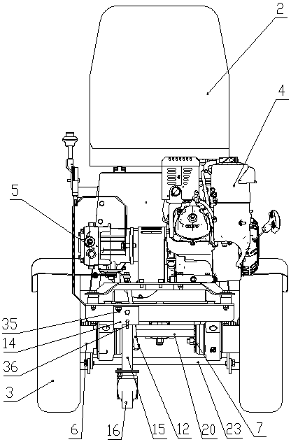
[0029] Such as Figure 1 to Figure 5 shown in figure 1 The right side is forward of the present invention, and the marking machine booster of the present invention comprises vehicle frame 1, seat 2, two driving wheels 3, power transmission system and braking system, and the front end of vehicle frame 1 and marking line The machine is detachably connected, the seat 2 is fixedly installed above the middle part of the vehicle frame 1, and the two driving wheels 3 are respectively located on the left and right sides of the middle part of the vehicle frame 1;

[0030] The power transmission system includes engine 4, hydraulic pump 5, hydraulic oil tank, reversing transmission mechanism, left wheel side motor 6 and right wheel side motor 7, engine 4, hydraulic pump 5 and hydraulic oil tank are all fixedly installed on the vehicle frame 1, hydraulic oil tank Blocked, not shown in the figure, the left wheel side motor 6 and the right wheel side motor 7 are respectively fixedly instal...


PUM


Abstract

A scriber booster comprises a vehicle frame, a seat, two driving wheels, a power transmission system and a brake system, wherein the power transmission system comprises an engine, a hydraulic pump, ahydraulic oil tank, a reversing transmission mechanism, a left wheel side motor and a right wheel side motor; the engine is connected with the hydraulic pump through a shaft coupler; an oil inlet of the hydraulic pump is connected with the hydraulic oil tank through a hydraulic pipe; the reversing transmission mechanism comprises walking pedals, a reversing rotating shaft, a reversing connecting block and a pull rod; the reversing rotating shaft is rotationally connected with the vehicle frame; the reversing rotating shaft stretches out of the vehicle frame and is fixedly connected with the walking pedals; the brake system is arranged at the front part of the vehicle frame; and a vehicle frame supporting device is downwardly arranged at the back part of the vehicle frame. The engine of thescriber booster is directly linked to the hydraulic pump through the shaft coupler, power of the scriber booster is directly supplied by the two wheel side motors, and through rotation of the walkingpedals, a reversing valve of the hydraulic pump is driven to achieve control of the walking direction; and the scriber booster is low in power loss, compact, and convenient to transport and use on aconstruction site.

Description

technical field [0001] The invention belongs to the technical field of marking construction equipment, and relates to a marking machine booster. Background technique [0002] Road markings refer to signs on the road surface that use lines, arrows, text, facade marks, raised road signs and contour marks to convey traffic information such as guidance, restrictions, and warnings to traffic participants. Its function is to control and guide traffic, and it can be used in conjunction with signs or alone. The marking machine is a road construction machine widely used in roads, highways, parking lots, squares and runways to draw different restrictions, guidelines and warnings on the flat ground. With its fast, efficient, accurate and other advantages, the marking machine has played a huge role in urban planning and road construction, saving the construction period and economic investment of road construction to the greatest extent. [0003] Most of the current marking machines ar...

Claims


Application Information

Patent Timeline
Patent Type & Authority Applications(China)
IPC IPC(8): E01C23/20
Inventor 袁中强张淑民王洋洋
Owner WELL ROAD MACHINERY CO LTD
Why Eureka
Eureka Blog
Learn More