Centrifugal pump exhaust device, exhaust method and control system

A technology of an exhaust device and an exhaust method, which is applied to pump control, components of a pumping device for elastic fluid, pumps, etc., can solve the problems of inconvenient management and high labor costs, and achieve convenient management and reduce management costs. Effect

Inactive Publication Date: 2018-01-23
CHONGQING BOZHANG MECHANO ELECTRONICS EQUIP
View PDF6 Cites 1 Cited by
  • Summary
  • Abstract
  • Description
  • Claims
  • Application Information

AI Technical Summary

Problems solved by technology

[0003] Because centrifugal pumps are generally located in harsh environments or remote places, it not only causes a lot of inconvenience in management, but also has high labor costs.

Method used


Image

  • Centrifugal pump exhaust device, exhaust method and control system

Examples


Embodiment Construction

[0024] In view of this, the core of the present invention is to provide a centrifugal pump exhaust device, which not only facilitates the management of the centrifugal pump, but also can effectively reduce the cost.

[0025] Another core of the present invention is to provide a centrifugal pump exhaust method and a centrifugal pump control system.

[0026] In order to enable those skilled in the art to better understand the solution of the present invention, the present invention will be further described in detail below in conjunction with the accompanying drawings and specific embodiments.

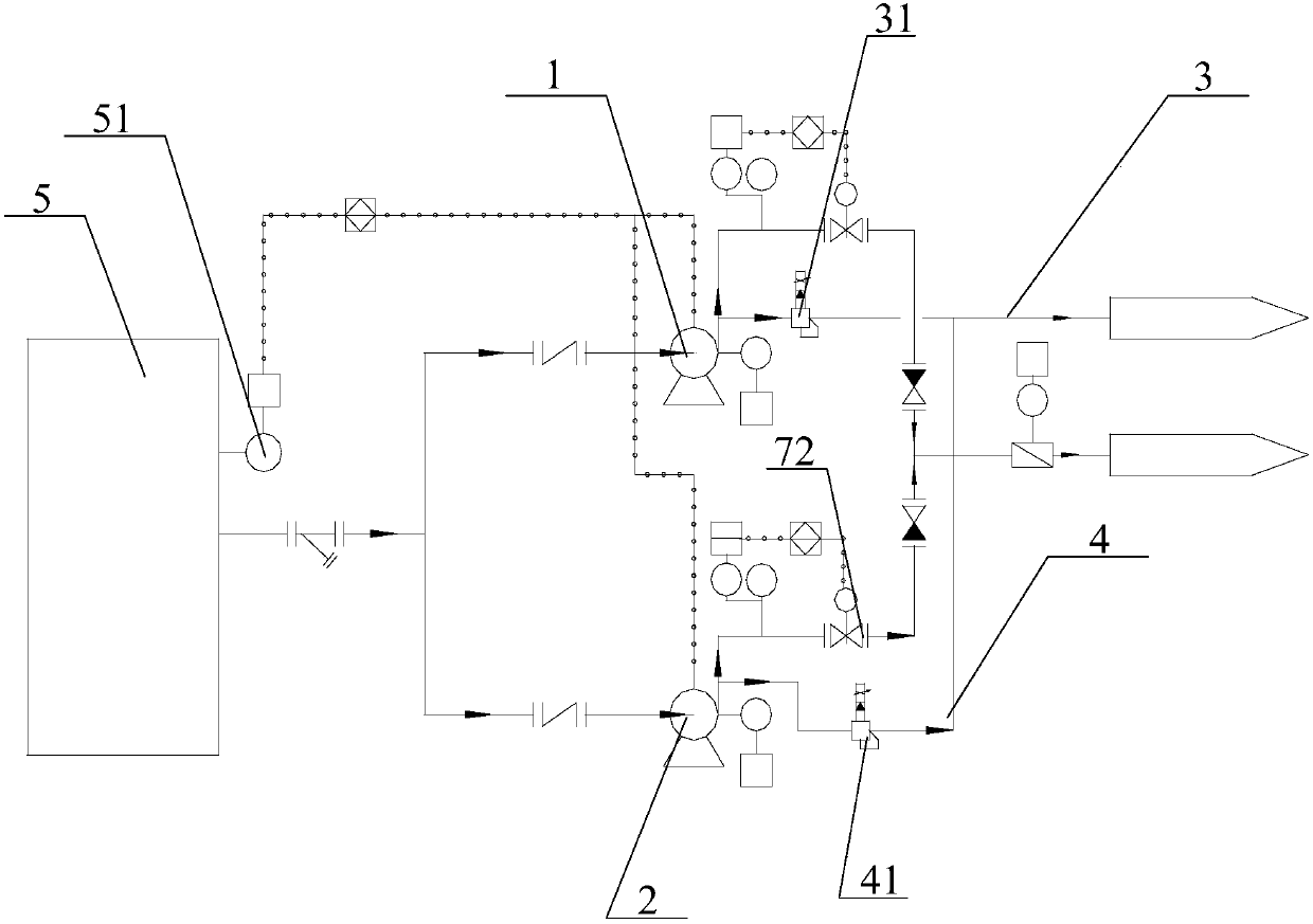
[0027] The embodiment of the present invention discloses a centrifugal pump exhaust device, which includes a centrifugal pump and a ventilation pipeline connected to the centrifugal pump. A switch is arranged on the ventilation pipeline, and the controller controls the opening or closing of the switch; When the liquid level sensor 51 detects that the liquid level in the liquid level body...


PUM


Abstract

The invention discloses a centrifugal pump exhaust device. The centrifugal pump exhaust device comprises a centrifugal pump, and a ventilation pipeline connected with the centrifugal pump; a switch isarranged on the ventilation pipeline; and a controller controls opening or closing of the switch. The centrifugal pump exhaust device further comprises a liquid level sensor for detecting a liquid level; when the liquid level sensor detects that the liquid level in a liquid box reaches a preset opening liquid level, the liquid level sensor transmits signals to the controller, and the controller controls opening of the switch; and after preset time, the controller controls closing of the switch, and the centrifugal pump is started to operate. The centrifugal pump exhaust device can realize automatic exhausting, is convenient to manage the centrifugal pump, and effectively reduces the management cost. The invention further discloses a centrifugal pump exhaust method and a centrifugal pump control system.

Description

technical field [0001] The invention relates to the technical field of centrifugal pumps, in particular to a centrifugal pump exhaust device, an exhaust method and a control system. Background technique [0002] Centrifugal pumps are mainly used for the transportation of water, oil, sewage and corrosive, toxic and other liquids. Before the centrifugal pump is started, the pump cavity and pipeline are filled with a large amount of air, and the liquid medium must be manually injected to drain the pump cavity and Only the air in the pipeline can pump out the liquid medium by the centrifugal force generated by the rotation of the impeller when the centrifugal pump starts, forming a sufficient vacuum in the pump chamber to continuously suck the liquid medium. [0003] Because centrifugal pumps are generally located in harsh environments or remote places, it not only causes a lot of inconvenience in management, but also has high labor costs. [0004] Therefore, how to provide a c...

Claims


Application Information

Patent Timeline
IPC IPC(8): F04D29/00F04D1/00F04D7/04F04D15/00
Inventor 张健
Owner CHONGQING BOZHANG MECHANO ELECTRONICS EQUIP
Why Eureka
Try Eureka