Pipeline leakage detection method and device

A pipeline leakage and detection method technology, which is applied in pipeline systems, mechanical equipment, gas/liquid distribution and storage, etc., can solve the problems affecting the promotion and application of negative pressure wave system positioning accuracy, unclear inflection point of negative pressure wave signal, and reduced acquisition accuracy and other problems, to achieve the effect of strong field operability, high positioning accuracy, and accurate acquisition

Active Publication Date: 2018-01-23
LASER RES INST OF SHANDONG ACAD OF SCI
View PDF5 Cites 21 Cited by
  • Summary
  • Abstract
  • Description
  • Claims
  • Application Information

AI Technical Summary

Problems solved by technology

However, due to the influence of factors such as signal attenuation and environmental noise during the transmission of the leaked negative pressure wave signal, the inflection point of the negative pressure wave signal is not clear, and the acquisition accuracy of the time difference between the sensors at both ends of the pipeline is reduced, which seriously affects the positioning accuracy and accuracy of the negative pressure wave system. Promotion and application in the pipeline transportation industry

Method used


Image

  • Pipeline leakage detection method and device
  • Pipeline leakage detection method and device
  • Pipeline leakage detection method and device

Examples


no. 1 example

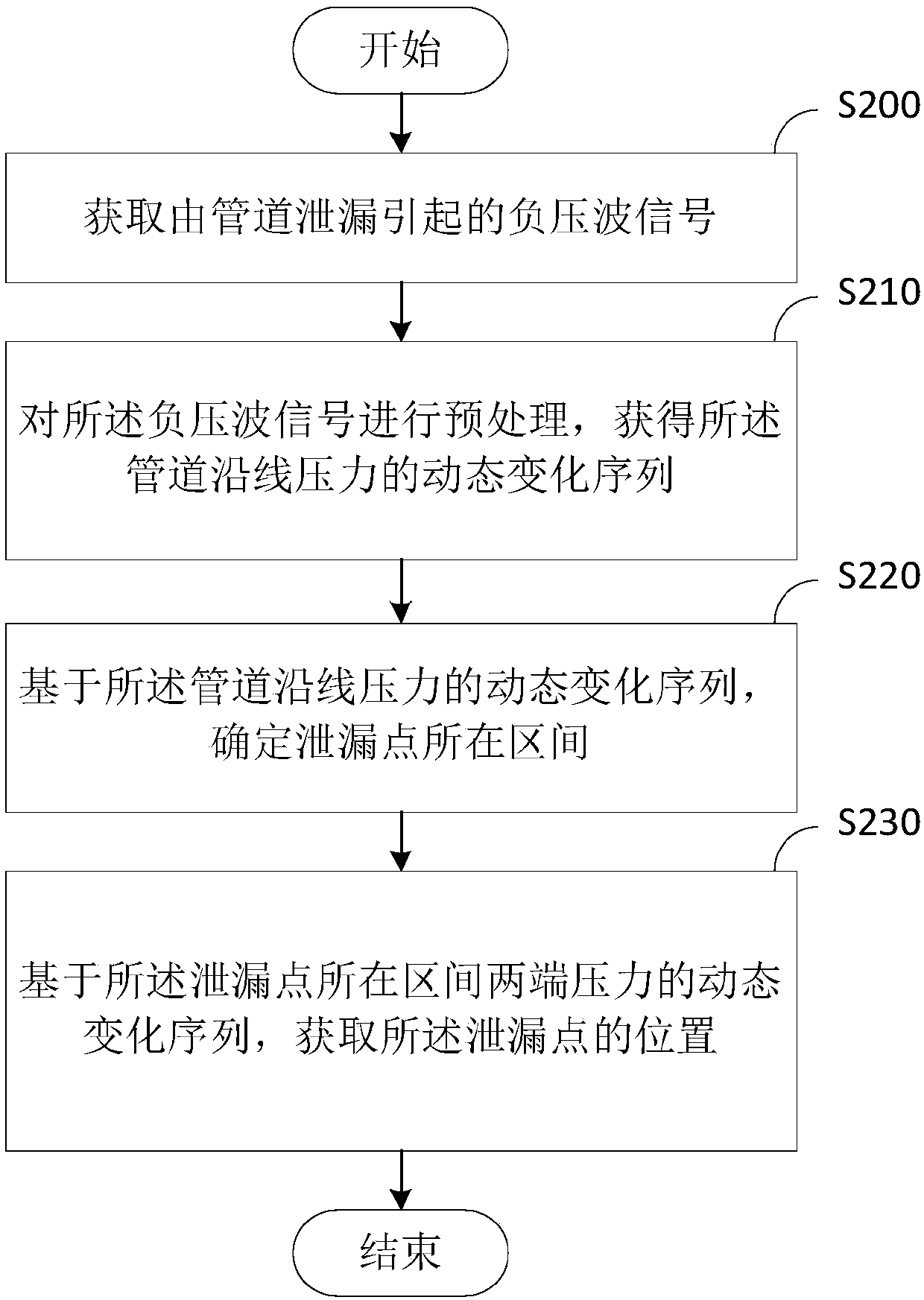
[0035] Please refer to figure 2 , the present embodiment provides a pipeline leak detection method, the method comprising:

[0036] Step S200: acquiring negative pressure wave signals caused by pipeline leakage;

[0037] In this embodiment, a plurality of sensors are arranged at intervals in the section to be tested of the pipeline, and each sensor can be used to obtain a pressure signal in the section to be tested. It can be understood that when a leak occurs in the pipeline to be tested, the pressure at the leakage point of the pipeline will drop suddenly due to the pipeline leakage, that is, a negative pressure wave signal will be generated, and the negative pressure wave signal will be obtained through sensor detection, namely Subsequent analysis of the position of the leakage point can be performed according to the negative pressure wave signal.

[0038] In this embodiment, the sensors may be electronic sensors or optical fiber sensors or other sensors capable of pipel...

no. 2 example

[0087] Please refer to Figure 11 , the present embodiment provides a pipeline leak detection device 600, which includes:

[0088] An acquisition module 610, configured to acquire negative pressure wave signals caused by pipeline leakage;

[0089] A preprocessing module 620, configured to preprocess the negative pressure wave signal to obtain a dynamic change sequence of pressure along the pipeline;

[0090] An interval module 630, configured to determine the interval where the leakage point is located based on the dynamic change sequence of the pressure along the pipeline;

[0091] The position module 640 is configured to obtain the position of the leak point based on the dynamic change sequence of the pressure at both ends of the interval where the leak point is located.

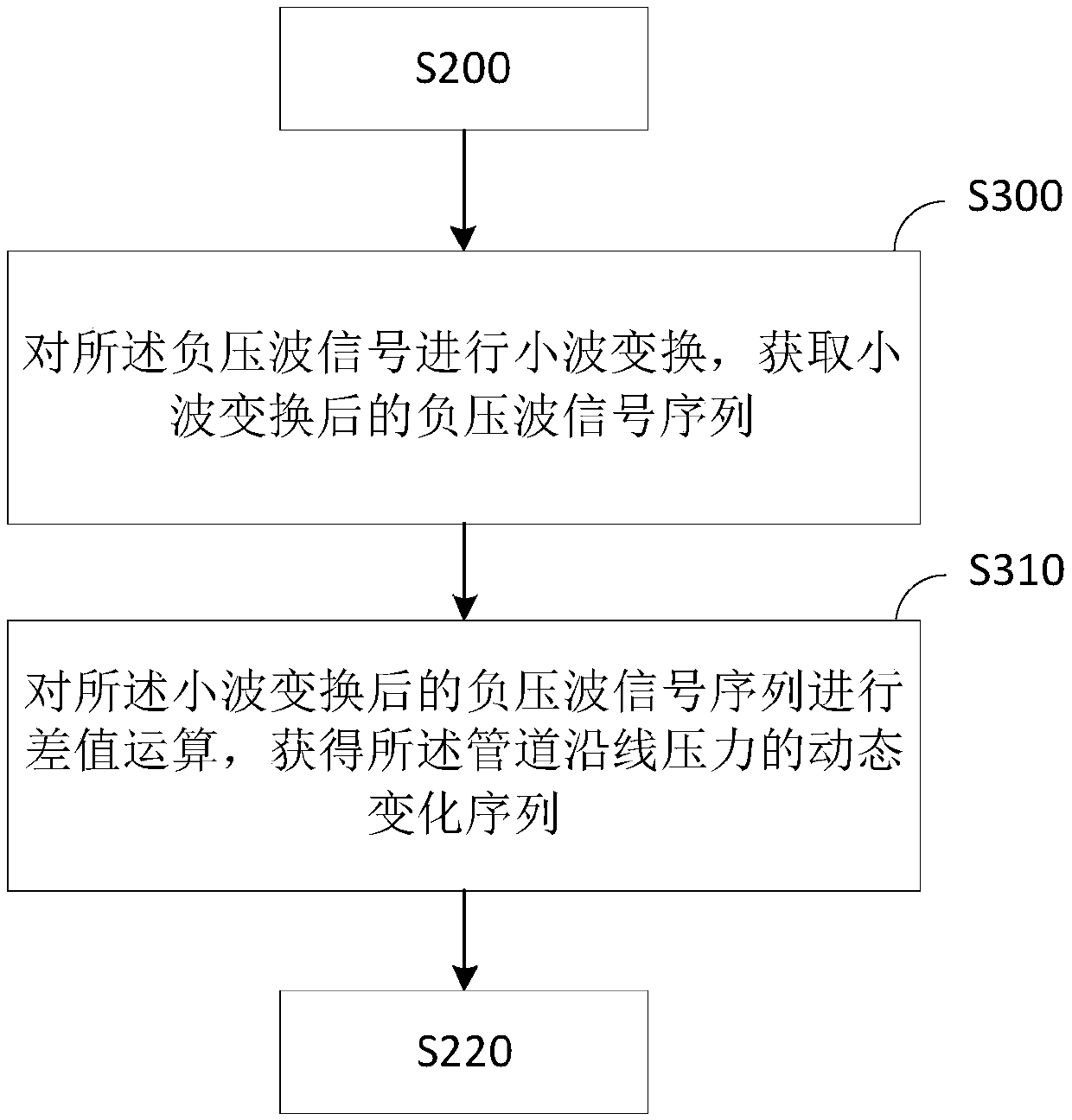
[0092] Please refer to Figure 12 , in this embodiment, further, the preprocessing module 620 may also include the following units:

[0093] A wavelet transformation unit 621, configured to perform wav...

no. 3 example

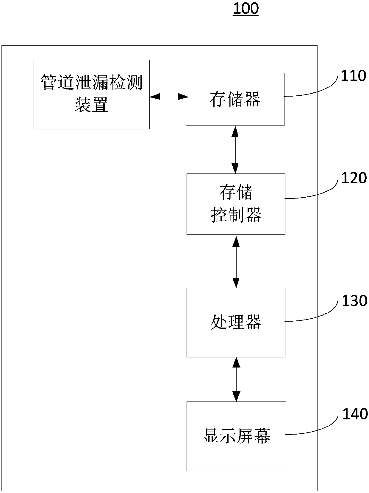
[0104] Please refer to Figure 15 , the present embodiment provides a pipeline leakage detection device 1000, which includes a plurality of sensors 800, and the multiple sensors 800 are arranged on the pipeline 900 to be tested at intervals along the axis of the pipeline to be tested 900.

[0105] In this embodiment, the distance between the plurality of sensors 800 is adjustable, and the sensors 800 are used to detect the negative pressure wave signal generated by the leakage of the pipeline 900 to be tested. Preferably, the distances between the plurality of sensors 800 are the same. It can be understood that the distances between the multiple sensors 800 may not be completely the same.

[0106] In this embodiment, the sensors 800 can be electronic sensors or optical fiber sensors or other sensors capable of pipeline pressure detection, and each of the sensors 800 can transmit the collected negative pressure wave signals to data in a wired or wireless manner. transmission....


PUM


Abstract

The invention provides a pipeline leakage detection method and device and relates to the field of pipeline leakage monitoring. The pipeline leakage detection method comprises the steps of obtaining anegative pressure wave signal caused by pipeline leakage; preprocessing the negative pressure wave signal to obtain the dynamic change sequence of pressure along a pipeline; determining the interval of a leakage point on the basis of the dynamic change sequence of pressure along the pipeline; and obtaining the position of the leakage point on the basis of dynamic change sequences of pressure at the two ends of the interval of the leakage point. According to the method and the device, the pipeline is detected in a segmented manner by multiple sensors arranged in the pipeline so as to determinethe interval of the leakage point, then the leakage point is positioned on the basis of the interval of the leakage point, the positioning precision is high, the site operability is high, and the method and the device can be widely applied to leakage detection of long oil and gas transmission pipelines and city water supply and heat supply pipelines.

Description

technical field [0001] The invention relates to the field of pipeline leakage monitoring, in particular to a pipeline leakage detection method and device. Background technique [0002] As the fifth largest mode of transportation, pipelines are the most effective way of transporting rheological media such as oil, natural gas, slurry, carbon dioxide, and biofuels. However, with the increase of pipe age, pipeline leakage accidents caused by aging corrosion, geological disasters and man-made damage occur frequently. Therefore, real-time monitoring of pipeline leakage and precise location of leakage points are of great significance to ensure public property and personal safety, protect the environment, and reduce national economic losses. [0003] Existing pipeline leakage detection technologies are mainly divided into four categories: leakage medium detection method, pipe wall parameter detection method, acoustic detection method and optical fiber distributed sensing monitoring...

Claims


Application Information

Patent Timeline
Patent Type & Authority Applications(China)
IPC IPC(8): F17D5/02
Inventor 赵林王纪强侯墨语李振刘媛
Owner LASER RES INST OF SHANDONG ACAD OF SCI
Why Eureka
Try Eureka