Light-emergent direction adjusting element and control method and display device thereof

A technology of direction adjustment and control method, which is applied in the manufacturing of optical components, electrical components, semiconductor/solid-state devices, etc., to achieve the effect of reducing manufacturing cost and structure thickness

Active Publication Date: 2018-01-23
BOE TECH GRP CO LTD
View PDF5 Cites 12 Cited by
  • Summary
  • Abstract
  • Description
  • Claims
  • Application Information

AI Technical Summary

Problems solved by technology

[0003] However, for current display devices, in order to switch between a small viewing angle and a large viewing angle, a scattering layer

Method used


Image

  • Light-emergent direction adjusting element and control method and display device thereof
  • Light-emergent direction adjusting element and control method and display device thereof
  • Light-emergent direction adjusting element and control method and display device thereof

Examples


Embodiment Construction

[0057] Reference will now be made in detail to the exemplary embodiments, examples of which are illustrated in the accompanying drawings. When the following description refers to the accompanying drawings, the same numerals in different drawings refer to the same or similar elements unless otherwise indicated. The implementations described in the following exemplary examples do not represent all implementations consistent with the present invention. Rather, they are merely examples of apparatuses and methods consistent with aspects of the invention as recited in the appended claims.

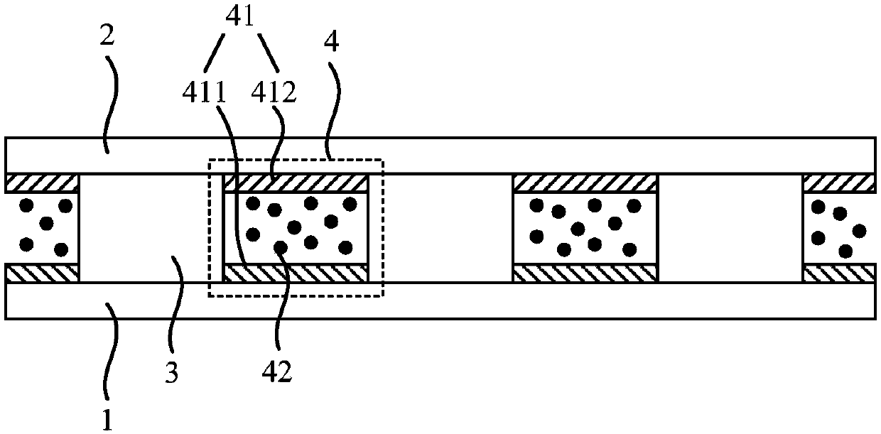
[0058] figure 2 It is a schematic structure diagram of a light emitting direction adjusting element according to an embodiment of the present invention. The light emitting direction adjusting element in this embodiment can be applied to various display modules, such as liquid crystal display modules and organic light emitting diode display modules. like figure 2 As shown, the light output d...


PUM


Abstract

The invention relates to a light-emergent direction adjusting element. The light-emergent direction adjusting element comprises a first substrate, a second substrate opposite to the first substrate, and light-permeable parts arranged between the first substrate and the second substrate. Adjusting parts are arranged between every two adjacent light-permeable parts. Each adjusting part comprises anelectrode control unit and charged light shielding particles, wherein the charged light shielding particles are used for shielding light passing through the adjusting part under the control of the electrode control unit. By means of the element, by controlling the voltage input to a first electrode and a second electrode, the state of the charged light shielding particles in the adjusting parts can be adjusted, and therefore the angle of the emergent light shielded by the charged light shielding particles is adjusted, and the emergent direction of light is adjusted. Compared with the prior art, no scattering layer needs to be arranged, the manufacturing cost can be easily reduced, and the structure thickness can be easily reduced.

Description

technical field [0001] The invention relates to the field of display technology, in particular to a light-emitting direction adjusting element, a display device, and a control method for the light-emitting direction adjusting element. Background technique [0002] The current anti-peeping display device is mainly realized by narrowing the display viewing angle. For example, in a liquid crystal display module, a light-shielding film layer is provided between the display panel and the backlight module, and a light-shielding part and a light-transmitting part are arranged at intervals. For details, see figure 1 , the light emitted by the backlight module is only the light with a small exit angle (such as figure 1 Middle α) can be emitted from the light-shielding film layer, and the light with a larger exit angle (such as figure 1 Middle β) will be absorbed by the irradiated light-shielding part, so that the light-shielding film layer cannot be emitted, and only the light with...

Claims


Application Information

Patent Timeline
IPC IPC(8): G02F1/1335G02F1/133H01L51/52
CPCG02F1/1323G02F1/133512G02F1/167G02F2201/44G02F1/1677G02B2207/123G02F2201/122G02F1/16756G02F1/1676G02F1/133607
Inventor 王英涛姚继开
Owner BOE TECH GRP CO LTD
Why Eureka
Try Eureka