Low-drop-out voltage stabilizer

A low-dropout voltage regulator and error amplifier technology, which is applied in the direction of instruments, electric variable adjustment, control/regulation systems, etc., can solve problems such as system instability and phase drop, and achieve the effect of high and low frequency gain

Active Publication Date: 2018-01-23
SOUTH CHINA UNIV OF TECH
View PDF4 Cites 6 Cited by
  • Summary
  • Abstract
  • Description
  • Claims
  • Application Information

AI Technical Summary

Problems solved by technology

[0010] However, for a more advanced process (such as 65nm), this pair of complex ...

Method used


Image

  • Low-drop-out voltage stabilizer
  • Low-drop-out voltage stabilizer
  • Low-drop-out voltage stabilizer

Examples


Embodiment 1

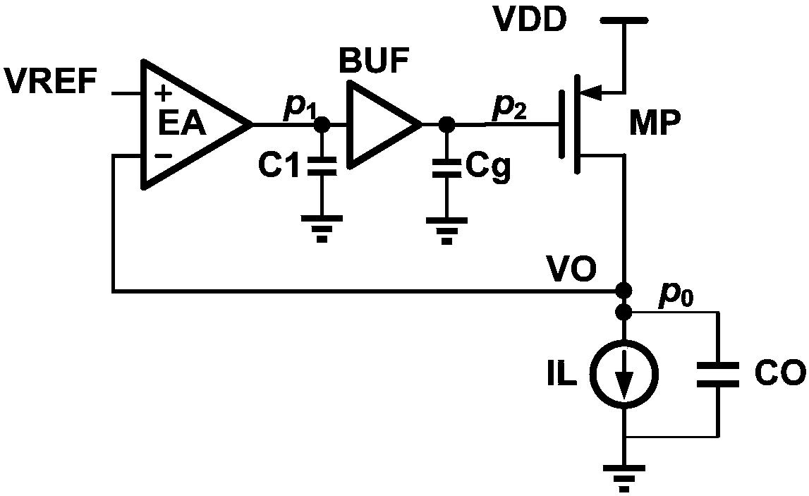
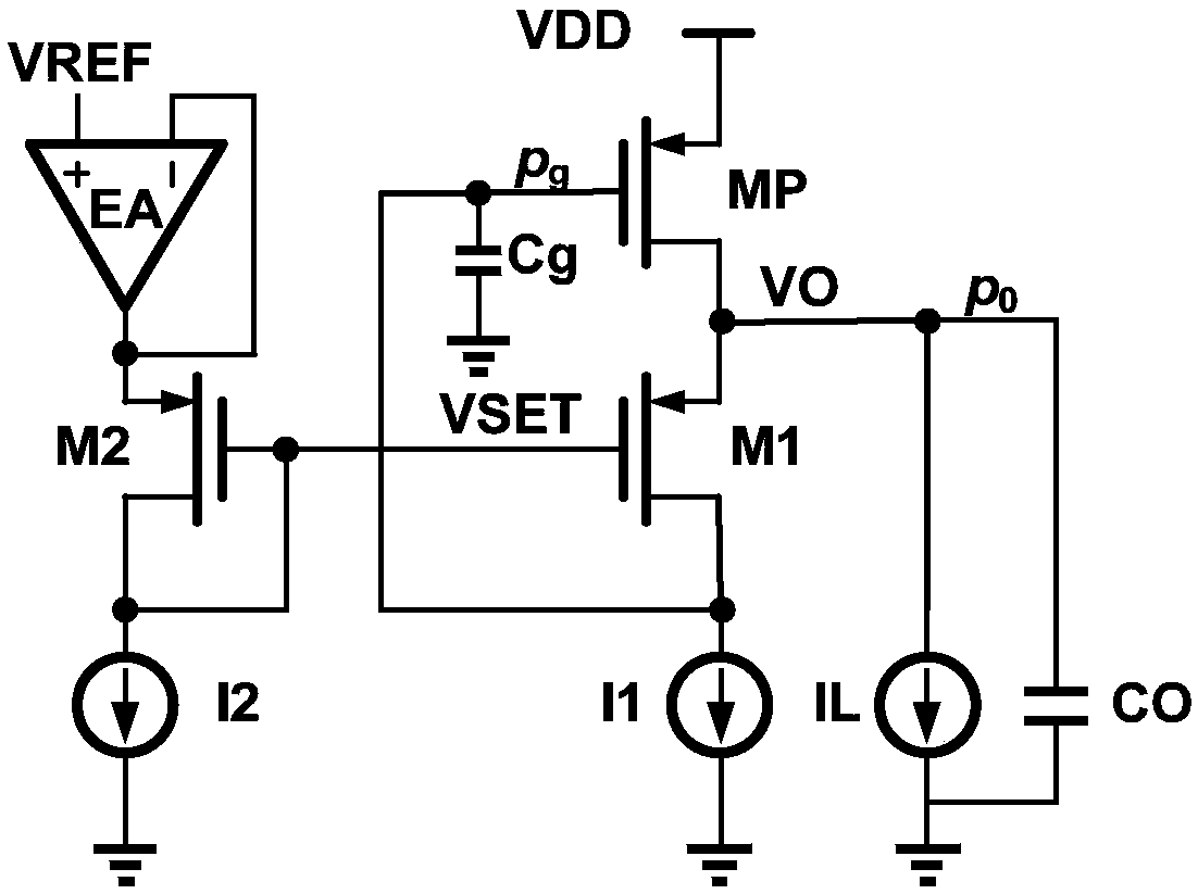
[0046] see Figure 7 , which is a structural diagram of the low dropout voltage regulator according to Embodiment 1 of the present invention. The present invention provides a high-speed and stable low-dropout voltage regulator, including an error amplifier EA, a first field effect transistor M1, a second field effect transistor M2, a power device MP, a first current source I1, a second current source I2, A load current source IL, a first capacitor CO, a second capacitor Cg, a third capacitor Cm and a super source follower SSF.

[0047] The positive input terminal of the error amplifier EA receives the reference voltage VDD, and the negative input terminal is connected to the output terminal.

[0048] The drain of the second field effect transistor M2 is connected to the output terminal of the error amplifier EA, the source is grounded through the second current source I2, and the gate is grounded through the second current source I2.

[0049] The drain of the power device MP...

Embodiment 2

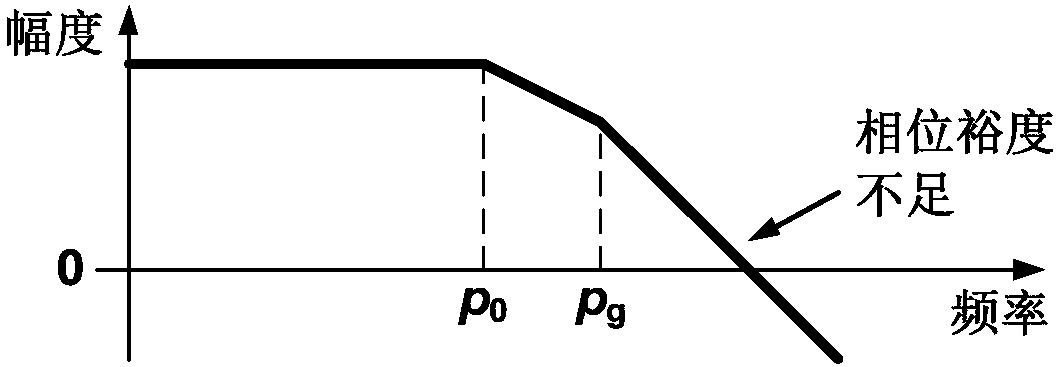
[0065] Compared with Embodiment 1, the main configuration of the damping coefficient control module of Embodiment 2 is different. Specifically, see Figure 11 , which is a structural diagram of the low dropout voltage regulator of the second embodiment. The damping coefficient control module DFC includes a fifth field effect transistor M5, a fourth capacitor C D and a fifth current source I5. The drain of the fifth field effect transistor M5 is connected to the power supply voltage VDD, the gate of the fifth field effect transistor M5 is connected to the gate of the fourth field effect transistor M4, and the source of the fifth field effect transistor M5 passes through the fifth field effect transistor M5. The current source I5 is grounded; the fourth capacitor C D The two ends of are respectively connected to the gate and the source of the fifth field effect transistor M5.

[0066] In this embodiment 2, the DFC module consists of M5, I5 and C D constitute. Among them, M...


PUM


Abstract

The invention provides a low-drop-out voltagestabilizer. The low-drop-out voltagestabilizer comprises an error amplifier, a second field effect tube, a power device, a first field effect tube and a super source follower, wherein the positive electrode input end of the error amplifier receives reference voltage, and the negative electrode input end is connected with the output end, the drain electrode of the second field effect tube is connected with the output end of the error amplifier, the source electrode of the second field effect tube is grounded through a second current source, and the grid electrode of the second field effect tube is grounded through a second current source; the drain electrode of the power device is connected to the power voltage, the drain electrode of the power device is connected with the drain electrode of the first field effect tube, and meanwhile, the power device is grounded through a first capacitor, grounded through a load current source and grounded through a third capacitor and a first current source; the grid electrode of the first field effect tube is connected with the grid electrode of the second field effect tube, the drain electrode of thefirst field effect tube is connected with the source electrode of the power device, and the source electrode of the first field effect tube is grounded through the first current source and meanwhile connected with the input end of the super source follower; the output end of the super source follower is connected with the grid electrode of the power device and meanwhile grounded through a second capacitor.

Description

technical field [0001] The invention relates to a low-drop voltage stabilizer, in particular to a high-speed and stable low-drop voltage stabilizer. Background technique [0002] see figure 1 , which is a structural diagram of a low dropout voltage regulator in the prior art. The most basic LDO structure of the LDO in the prior art is as follows: figure 1 shown. For an indeterminate input (supply voltage VDD), the output voltage VO can always be kept equal to the reference voltage VREF. This is because VO and VREF are connected to the two inputs of an error amplifier. The error amplifier (EA) and the high gain of the entire loop make the EA input virtual short, that is, VO=VREF. [0003] When the load current IL jumps, in order to stabilize VO, a large output capacitor CO is needed to provide the current change required by IL when the LDO loop has no time to respond. [0004] On the other hand, in order to provide the required large current, the power device MP usually...

Claims


Application Information

Patent Timeline
IPC IPC(8): G05F1/56
Inventor 黄沫
Owner SOUTH CHINA UNIV OF TECH
Why Eureka
Try Eureka