Converter control device

A technology for control devices and converters, applied in harmonic reduction devices, power amplifiers, and AC networks to reduce harmonics/ripples, etc. The coupling method lacks reports and other problems to achieve the effect of eliminating grid impedance

Active Publication Date: 2018-01-23
浙江知多多网络科技有限公司
View PDF5 Cites 7 Cited by
  • Summary
  • Abstract
  • Description
  • Claims
  • Application Information

AI Technical Summary

Problems solved by technology

When the number of grid-connected converters connected in parallel at the public end of the grid increases, this difficulty increases, and even threatens the safe and stable operation of the grid
At present, most of the research is still focused on proposing corresponding control methods by establishing a specific mathematical model of distributed grid-connected power generation system and predicting grid impedance by using harmonic injection. The complete decoupling method of the lack of reports

Method used


Image

  • Converter control device
  • Converter control device
  • Converter control device

Examples


Embodiment Construction

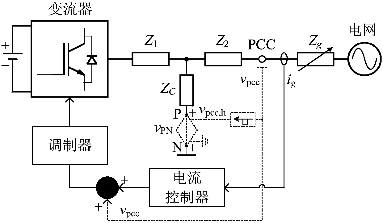
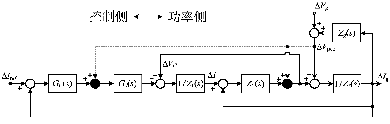
[0028] figure 1 It is a schematic diagram of a grid-connected converter including a grid decoupling control unit and device. It consists of a converter and a grid decoupling unit. The grid decoupling unit includes a common terminal grid voltage unit feedforward control and a filter capacitor branch connected in series. The equivalent voltage source v PN . Its corresponding control block diagram is as follows figure 2 As shown, the dotted line part is the power grid decoupling part. figure 2 The common terminal grid voltage signal injected by the control side represents the unit feedforward control, and the grid voltage signal injected by the power side is realized by the active power conversion device. E.g:

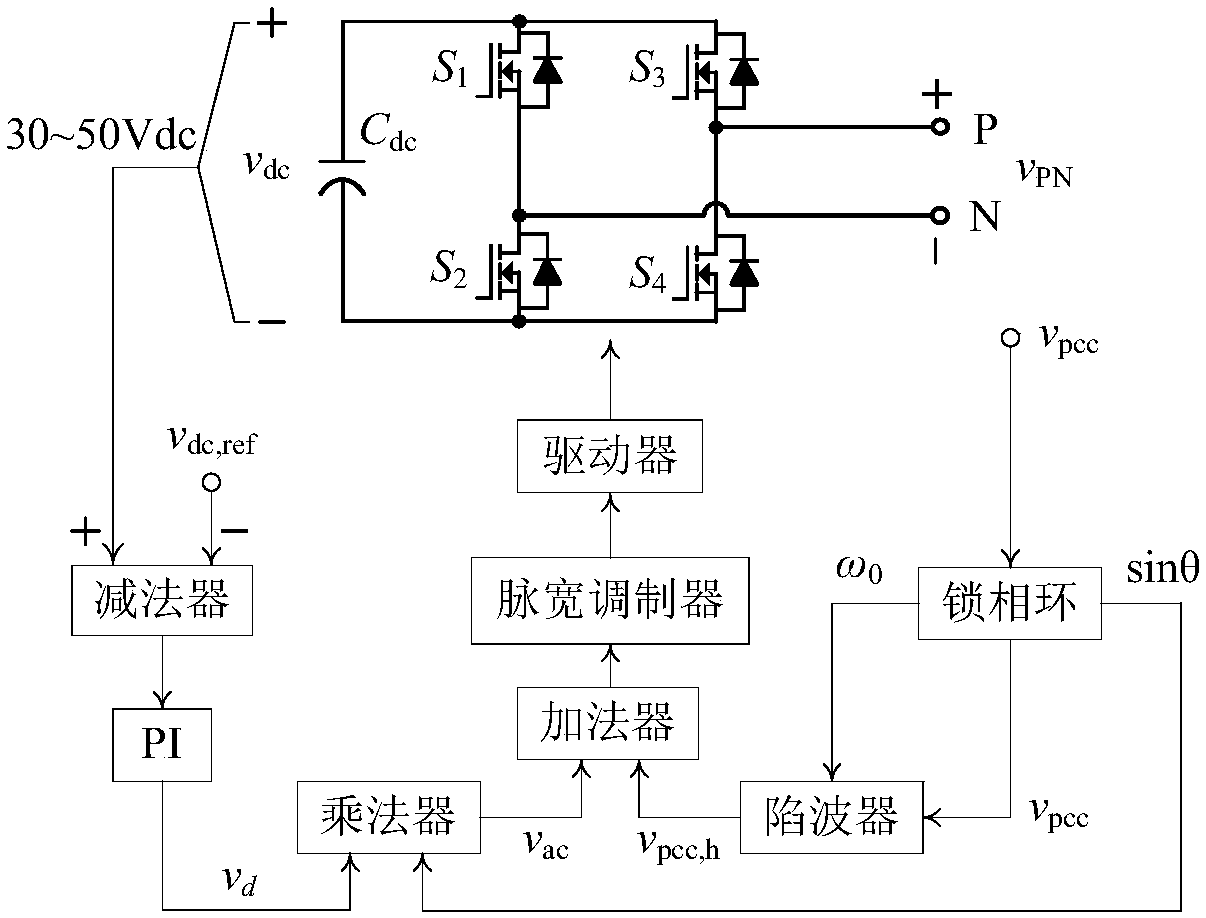
[0029] image 3 Shown is the use of an active bidirectional power converter to achieve an equivalent voltage source v PN . v PN Contains power frequency signal v ac and the harmonic signal v pcc,h , where v ac is used to guarantee the DC capacitor voltage v ...


PUM


Abstract

The invention discloses a converter control device. Due to the uncertainty of power grid conditions, the problems of access current harmonic amplification, power fluctuation, converter instability andthe like of a converter caused by impedance mismatching (a weak power grid) can be caused to endanger the safety of the converter and to shorten the life of the converter when the grid-connected converter is accessed under different power grid conditions, so that matching of output impedance of the converter under different power grid conditions and power grid impedance needs to be ensured to reduce the mutual influence of the converter and the power grid. By adopting a strategy of connecting a group of active power conversion devices to a grid-connected filter capacitor branch of the converter in series, the power grid impedance and the grid side harmonic component are eliminated and complete decoupling of the power grid is achieved through combining a common terminal (PCC terminal) grid-voltage unit feedforward control unit with the active devices.

Description

technical field [0001] The invention belongs to the technical field of converter control in AC and DC power grids, and in particular relates to a power grid decoupling control device and method suitable for a new energy distributed grid-connected converter based on LCL filter output. Background technique [0002] With the increase of global energy crisis and environmental pressure, new energy distributed generation technology has attracted much attention. The new energy distributed generation system usually consists of multiple grid-connected power converters to convert renewable energy into AC or DC and connect it to the grid. When the internal resistance of the power grid is zero or almost zero, the current injected into the power grid will hardly affect the power grid voltage. This kind of power grid is usually called a strong power grid; when the internal resistance of the power grid cannot be ignored, the power grid voltage will If the output impedance of the grid-conn...

Claims


Application Information

Patent Timeline
Patent Type & Authority Applications(China)
IPC IPC(8): H02J3/38H02J3/01H03F3/20
CPCY02E40/40
Inventor 何远彬杭丽君谢小高刘士荣
Owner 浙江知多多网络科技有限公司
Why Eureka
Try Eureka