
Selective laser melting device

A technology of laser selective melting and equipment, applied in the direction of additive processing, etc., can solve the problems of finished products such as porosity, inclusions, crack enlargement, affecting the quality of the finished product, falling on the powder bed, etc., to improve the quality of the finished product, ensure the accuracy uniform effect

Pending Publication Date: 2018-01-26
TSC LASER TECH DEV BEIJING CO LTD
View PDF5 Cites 4 Cited by
  • Summary
  • Abstract
  • Description
  • Claims
  • Application Information

AI Technical Summary

Problems solved by technology

However, there are unavoidable defects in the flexible powder spreading device. When the scraper passes the high point, this high point is very likely to become a source of defects, which increases the probability of air holes, inclusions, cracks, etc. in the finished product
In addition, most of the waste slag generated during the processing is taken away by the circulating air, but a small part will fall on the powder bed. After the waste slag falls into the powder bed, it also forms high points. The flexible powder spreading device cannot take away these high point waste slag , but press it into the powder bed, affecting the quality of the final product
[0004] It can be seen that the above-mentioned existing laser selective melting equipment obviously still has inconvenience and defects in structure, method and use, and needs to be further improved urgently.

Method used


Image

  • Selective laser melting device
  • Selective laser melting device
  • Selective laser melting device

Examples


Embodiment Construction

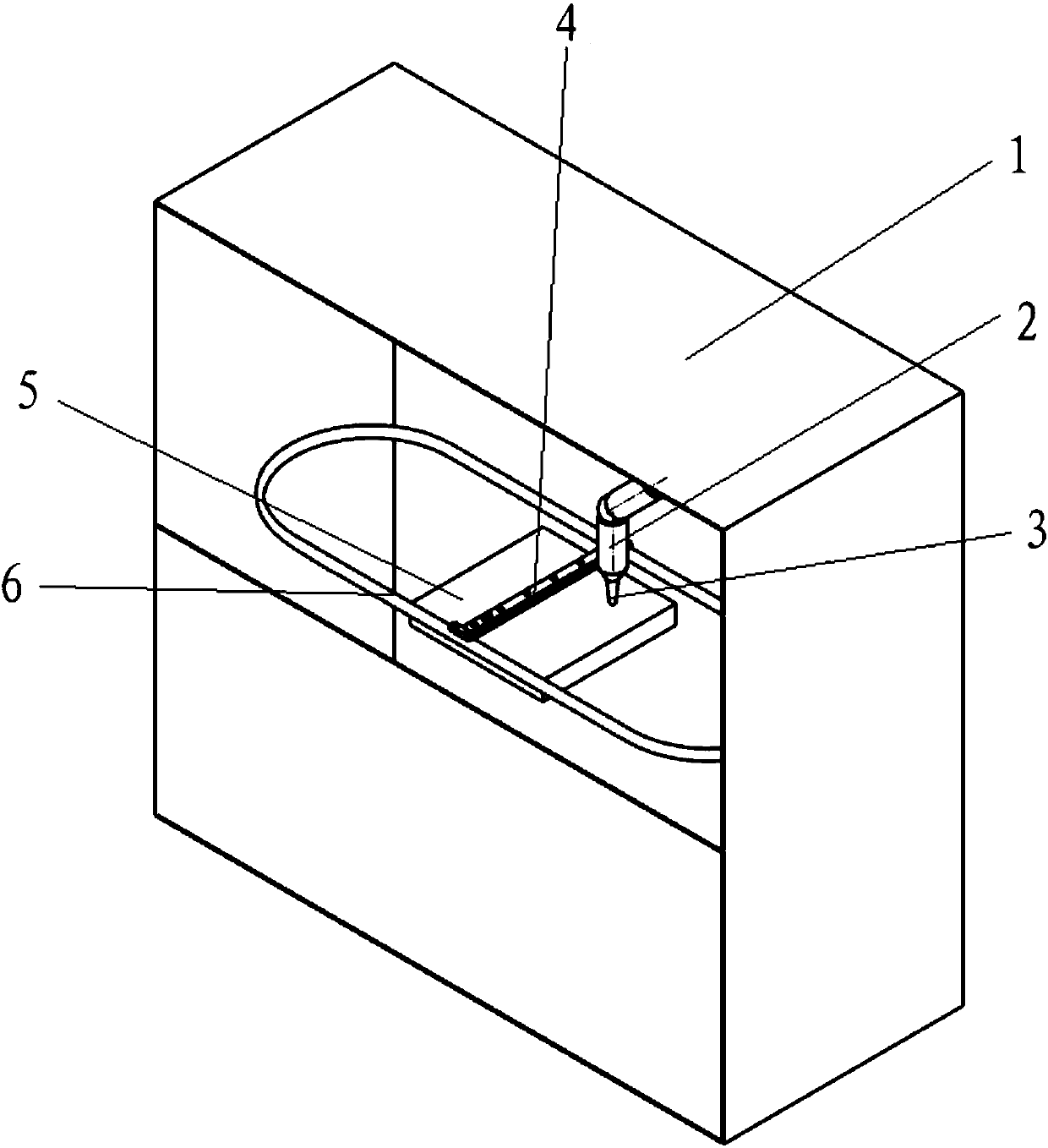
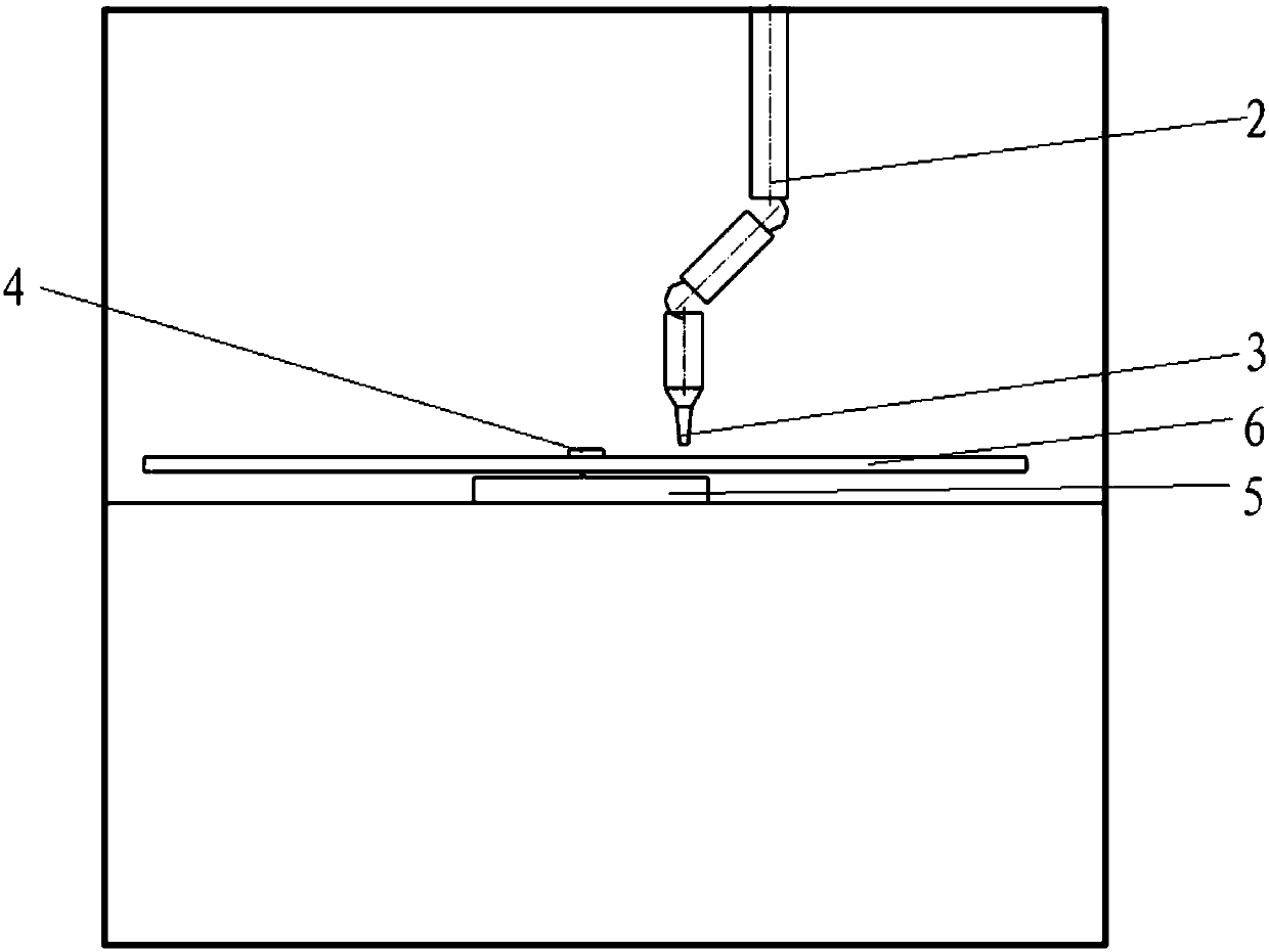
[0026] Refer to attached figure 1 and 2 As shown, the laser selective melting equipment of the present invention includes a rigid powder spreading device, a milling cutter cutting device and a control device. Both the rigid powder spreading device and the milling cutter cutting device are arranged in the processing chamber 1 of the laser selective melting equipment.

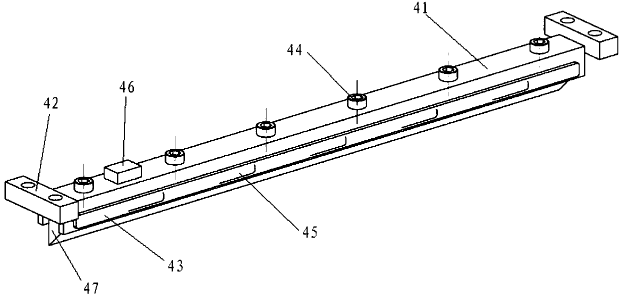
[0027] The rigid powder spreading device includes a scraper mechanism 4 , a rail mechanism 6 , a power mechanism and an overload current detection mechanism 46 . The scraper mechanism 4 is used to realize the rigid powder spreading action of the selective laser melting equipment. The guide rail mechanism 6 can adopt any existing guide rail structure, and a circular track structure is adopted in this embodiment. The power mechanism drives the scraper mechanism 4 to move along the guide rail of the guide rail mechanism 6 to realize the rigid powder spreading action of the scraper on the surface of the molten lay...


PUM


Abstract

The invention discloses a selective laser melting device. The selective laser melting device comprises a rigid powder laying device, a milling tool cutting device and a control device. The rigid powder laying device comprises a scraping knife mechanism, a guide rail mechanism, a power mechanism and an overcurrent detection mechanism. The power mechanism drives the scraping knife mechanism to movealong the guide rail mechanism. The overcurrent detection mechanism is arranged on the scraping knife mechanism and is connected with the control device. The milling tool cutting device comprises a mechanical arm and a milling tool. The control device is used for receiving and analyzing detection information transmitted by the overcurrent detection mechanism and controls the mechanical arm and themilling tool to realize the high point cutting action according to the detection information. The selective laser melting device conducts forced scraping on high points by means of the rigidity of ascraping knife in the powder laying process. If the high points are cut off by the scraping knife, the powder laying action can be completed smoothly. If the scraping knife gets stuck, cutting of thehigh points is realized through monitoring of the overcurrent detection mechanism and cutting of the milling tool cutting device. It is guaranteed that no high point exist in the manufacturing process. The defect rate of parts is greatly reduced. The precision of the parts is improved.

Description

technical field [0001] The invention relates to the technical field of laser selective melting, in particular to a laser selective melting device. Background technique [0002] Additive Manufacturing (AM) technology is a technology that uses the method of gradually accumulating materials to manufacture solid parts. Compared with the traditional material removal-cutting technology, it is a "bottom-up" manufacturing method. Selective Laser Melting (SLM) direct manufacturing technology, also known as metal 3D printing technology, is the cutting-edge technology of additive manufacturing. Before processing, first slice and discretize the CAD model of the part through professional data processing software and add necessary support structures, and then plan the scanning path. The processed data will contain contour information that can control the movement of the laser beam. Then import this data into the molding equipment, the computer transfers the profile information layer by l...

Claims


Application Information

Patent Timeline
Patent Type & Authority Applications(China)
IPC IPC(8): B22F3/105B33Y30/00B33Y50/02
Inventor 马英杰李广生孙峰
Owner TSC LASER TECH DEV BEIJING CO LTD
Learn More