

Anchor section joint type segmental arc inhibiting device of railway overhead line and its method
A suppression device and electric segmentation technology, applied in the direction of power lines, transportation and packaging, vehicle parts, etc., can solve problems such as catenary disconnection, and achieve the effects of improved reliability, high reliability, and long life
- Summary
- Abstract
- Description
- Claims
- Application Information
AI Technical Summary
Problems solved by technology
Method used
Image

Examples
Embodiment 1
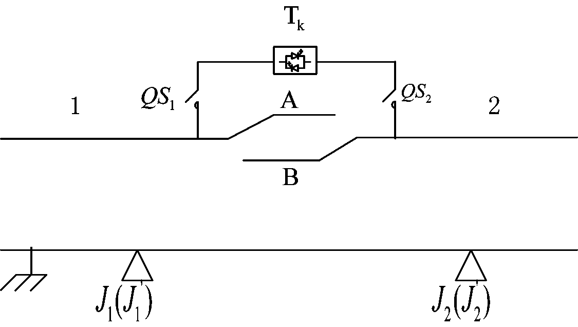
[0031] Such as figure 2 As shown, the present invention discloses a railway catenary anchor section joint-type electric segment arc suppression device, through specific control, when the train is segmented by electricity, no arc and overvoltage will be generated, which can fundamentally solve the problem. At present, there are problems of overvoltage, electric arc, burning bow and disconnection in the catenary anchor type electric section, including the power electronic solid-state switch connected across the two ends of the electric section and connected in series with power electronic solid-state switches Internet isolation switch at both ends and , also includes two pairs of train position detection sensors J located on the rails on both sides of the electric segment 1 (J 1 ’ ) and J 2 (J 2 ’ ), detect and identify the wheelset signal through the sensor, detect whether the train has reached the detection interval P1-P2 of the electric segment, and the power el...
Embodiment 2
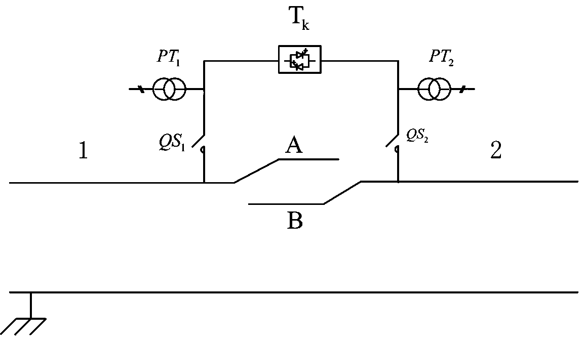
[0035] Such as image 3 As shown, the difference from Embodiment 1 is that the detection interval P1-P2 is identified in a different way. The realization method is to use high-precision voltage transformer PT 1 and high precision voltage transformer PT 2 The voltages at both ends of the jointed electrical segment of the anchor segment are measured respectively, and the voltage difference at both ends of the electrical segment is calculated by the difference measured by the two voltage transformers.
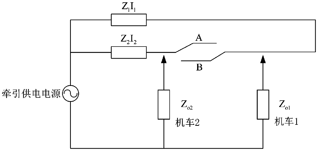
[0036] Due to the line impedance and load dispersion on the power supply partitions at both ends of the electric section in the project, there must be a voltage difference between the two ends of the electric section. As mentioned in the background, when the train pantograph passes through the electric section, there will be a voltage difference In the process of short-circuiting the two power supply partitions of the section, the voltage difference at both ends of the electric ...
Embodiment 3
[0039] Such as Figure 4 As shown, the difference from Embodiment 1 and Embodiment 2 is that the detection interval P1-P2 is identified in a different manner. The implementation is to install optical, microwave or radio frequency detection devices on the pillars beside the track at both ends of the electric section.
[0040] The optical identification device can be infrared or laser, and the basic principle is distance measurement, using the distance difference measured before and after the arrival of the train for identification.
[0041] Microwave and radio frequency identification devices are generally paired. The basic principle is to use radio waves to transmit and receive. When there is no object on the track, the radio wave signal can be received and sent normally. When there is an object on the track, the radio wave signal cannot be received and sent normally. Identification is detected by this method.
[0042] In order to improve the accuracy and reliability of this...
PUM
 Abstract
Description
Claims
Application Information