A device for simulating an image-rotating optical target

A target simulation and motion technology, which is used in measurement devices, optical instrument testing, machine/structural component testing, etc.

Active Publication Date: 2019-11-19
CHANGCHUN INST OF OPTICS FINE MECHANICS & PHYSICS CHINESE ACAD OF SCI
View PDF5 Cites 0 Cited by
  • Summary
  • Abstract
  • Description
  • Claims
  • Application Information

AI Technical Summary

Problems solved by technology

However, due to the inevitable errors in actual manufacturing and assembly, the focal length and other related optical indicators of multiple sets of optical collimation systems must be different from the actual design values.
This also leads to the fact that the various target motion control parameters set according to the theoretical values ​​of the optical collimation system are inconsistent with the actual situation, and then the moving targets located on the focal planes of multiple optical collimation systems in the space separation simulation optical path do not conform to the above-mentioned laws of motion. Three principles require

Method used


Image

  • A device for simulating an image-rotating optical target
  • A device for simulating an image-rotating optical target
  • A device for simulating an image-rotating optical target

Examples


Embodiment Construction

[0034] In order to enable those skilled in the art to better understand the technical solutions of the present invention, the present invention will be further described in detail below in conjunction with the accompanying drawings.

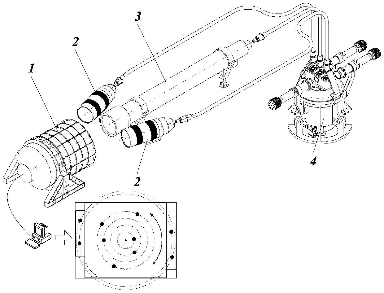
[0035] see Figure 1-3 shown;

[0036] An image rotation moving optical target simulation device of the present invention comprises:

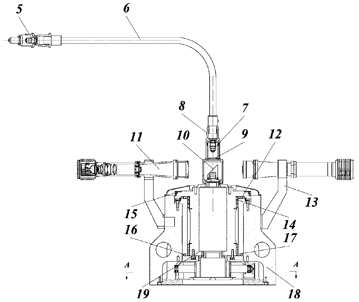
[0037] Target simulator base 18 has a cavity inside the target simulator base 18;

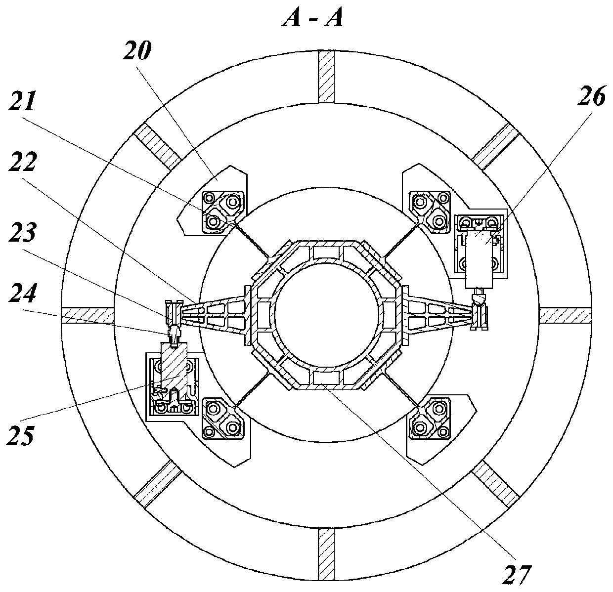
[0038] The torsion table, the torsion table is installed in the cavity of the base 18 of the target simulation device, and the torsion table includes a torsion shaft 19 and a torsion drive shaft 27 assembled in series with the torsion shaft 19, and the torsion table can rotate along the axial direction;

[0039] The upper part of the torsion shaft 19 is fixedly connected with three mounting frames side by side, and a reticle 9 is fixed inside each mounting frame, and each reticle 9 is engraved with star points with different geom...


PUM


Abstract

The invention discloses an image rotation optical target simulation device, which specifically includes a base of the target simulation device and a torsion platform, wherein, the upper part of the base of the target simulation device is fixedly connected with three mounting brackets side by side, and each of the mounting brackets A reticle is fixed inside the frame, each reticle is marked with star points with different geometric characteristics, and the torsion axis drives the three reticles to reciprocate torsion motion; the simulation device includes three Set of three uniform illumination optical systems, the image of the reticle is transmitted to the collimating optical system at the front end of the coupling objective lens assembly through a set of coupling objective lens assembly and optical fiber imaging beam assembly, and passed through the three collimating optical systems. The optical system projects images to different fields of view of the photoelectric imaging system to be tested at the front end of the simulation device. The present invention proposes a method based on the simulation of homologous moving targets, and then through the split coupling of the image-transmitting optical fiber bundle, so as to solve the current technical problems of asynchronous motion and inconsistent motion rules of large-field image-rotation targets.

Description

technical field [0001] The invention relates to the technical field of optical detection and optical measurement, in particular to a homologous, high-frequency image-rotation moving optical target simulation device mainly used in the testing and evaluation of space astronomical telescopes. Background technique [0002] A space astronomical telescope refers to a type of space optical payload mounted on a satellite platform for imaging and measuring various astronomical phenomena in the universe. For example, the well-known Hubble Telescope, Heschel Telescope, and Kepler Telescope are all typical space astronomical telescopes. The space astronomical telescope is different from the ground remote sensing system which adopts the continuous photography and imaging method of thrusting, but adopts the imaging method with a certain exposure time. In order to obtain stellar images of the early universe and improve the detection depth of the telescope, most of the above-mentioned spac...

Claims


Application Information

Patent Timeline
Patent Type & Authority Patents(China)
IPC IPC(8): G01M11/00
Inventor 何煦张晓辉姬琪杨雪
Owner CHANGCHUN INST OF OPTICS FINE MECHANICS & PHYSICS CHINESE ACAD OF SCI
Why Eureka
Try Eureka