
Multifunctional lathe cutting fluid filtration device

A filter device and cutting fluid technology, applied in the direction of filtration separation, fixed filter element filter, maintenance and safety accessories, etc., can solve the problems affecting the surface processing effect of the workpiece, shorten the service life of the cutting fluid, and affect the processing effect of the workpiece, etc., to achieve Simple structure, reliable operation, good practical effect

Pending Publication Date: 2018-01-30
平湖智铂自动化设备股份有限公司
View PDF0 Cites 5 Cited by
  • Summary
  • Abstract
  • Description
  • Claims
  • Application Information

AI Technical Summary

Problems solved by technology

[0002] During mechanical processing, it is often necessary to cool the cutting tools and workpieces in processing with cutting fluid. During the circulation process, the cutting fluid will bring the chips generated during processing to the cooling water tank, which will not only easily cause damage to the water pump, flushing pump, and pipeline in the water tank. And the water nozzle is blocked, which affects the cooling effect, and the cutting fluid mixed with chips is easy to cause secondary cutting on the workpiece, which affects the surface processing effect of the workpiece
In addition, during the lubrication process of the machine tool, the lubricating oil will also drip into the cutting fluid. If it is not removed in time, it will easily lead to the deterioration and thickening of the cutting fluid, thereby shortening the service life of the cutting fluid and increasing the cost of use; and the cutting fluid The oil slick in the oil will also affect the processing effect of the workpiece, especially the processing of high-gloss products
Existing cutting fluid filtration devices are generally only aimed at filtering chips, and there is currently no good solution for oil slicks in cutting fluids

Method used


Image

  • Multifunctional lathe cutting fluid filtration device
  • Multifunctional lathe cutting fluid filtration device

Examples


Embodiment

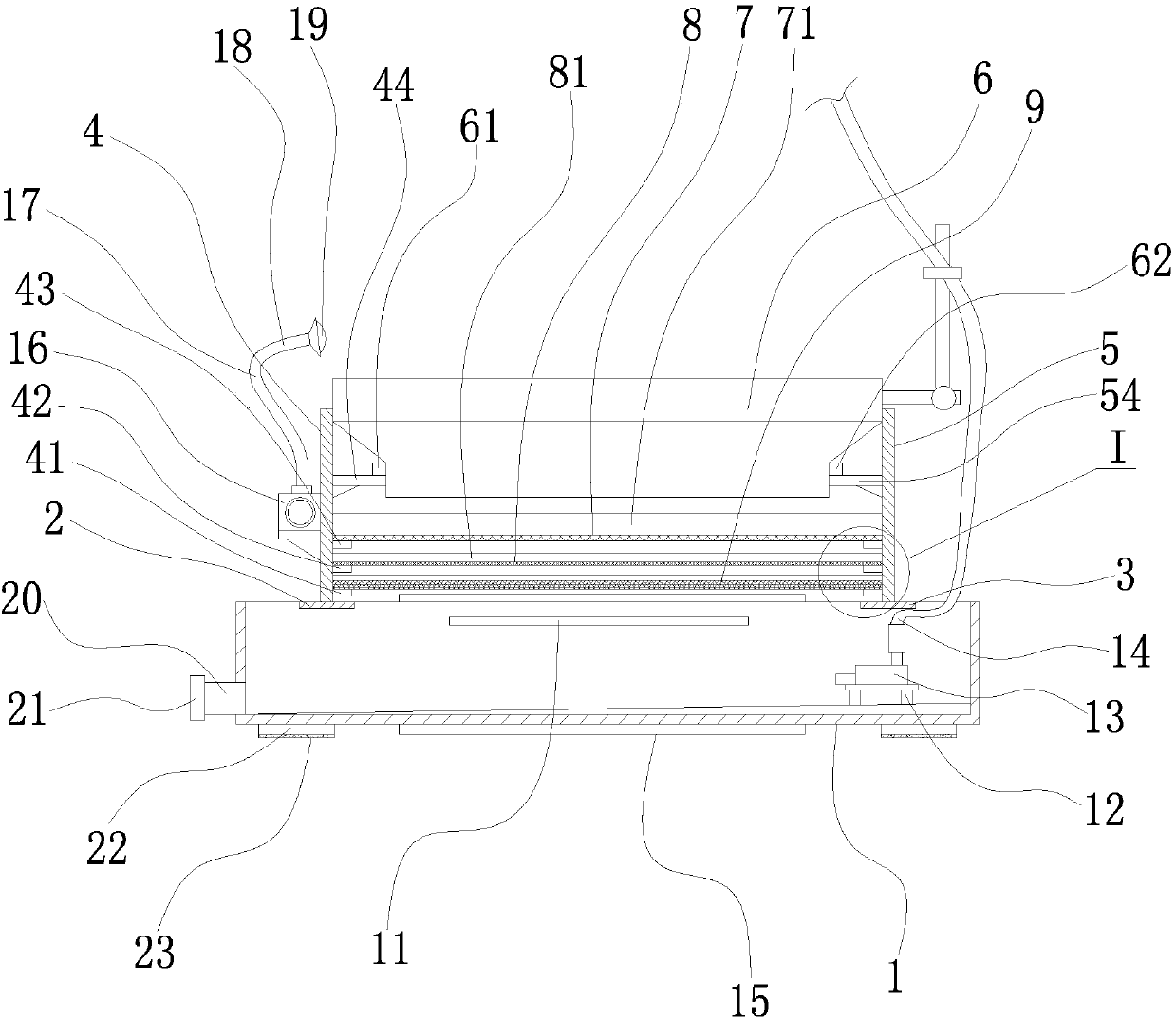
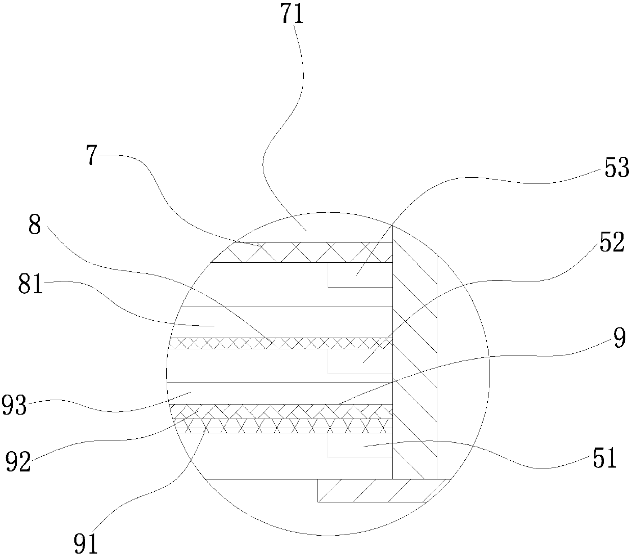
[0020] Example: such as figure 1 and figure 2 As shown, a multifunctional lathe cutting fluid filtering device includes a cutting fluid collection tank 1, the upper end of the cutting fluid collection tank 1 is fixedly provided with a left support plate 2 and a right support plate 3, and the left support plate 2 is fixed A first vertical support 4 is provided, and the right end surface of the first vertical support 4 is sequentially provided with a first positioning protrusion 41, a second positioning protrusion 42, a third positioning protrusion 43 and a first limit position from bottom to top. frame 44; the right support plate 3 is fixedly provided with a second vertical support 5, and the left end surface of the second vertical support 5 is sequentially provided with a fourth positioning projection 51, a fifth positioning projection 52, The sixth positioning projection 53 and the second limiting frame 54, a guide cover 6 is arranged between the first limiting frame 44 and...


PUM


Abstract

The invention relates to a multifunctional lathe cutting fluid filtration device which comprises a cutting fluid collection tank. A left supporting plate and a right supporting plate are fixedly arranged at the upper end of the cutting fluid collection tank, a first vertical support is fixedly disposed on the left supporting plate, and a second vertical support is fixedly disposed on the right supporting plate. A guide cover is disposed between a first limiting frame and a second limiting frame, a cutting fluid coarse filter screen is disposed between a third positioning bump and a sixth positioning bump, a cutting fluid refined filter screen is disposed between a second positioning bump and a fifth positioning bump, and a floating oil filter screen is disposed between a first positioningbump and a fourth positioning bump. The upper end of the rear end face of the cutting fluid collection tank is provided with a floating oil outlet, a water pump is detachably disposed on a water pumpsupport, and a liquid outlet of the water pump is in threaded connection with a cutting fluid conveying pipe. According to the technical scheme, the multifunctional lathe cutting fluid filtration device is reasonable in structural design, simple in structure and low in manufacturing cost, the filter screens are convenient to dismantle, and the multifunctional lathe cutting fluid filtration devicefacilitates clearing of cuttings and is convenient to use.

Description

technical field [0001] The invention belongs to the technical field of mechanical processing equipment, and in particular relates to a multifunctional lathe cutting fluid filtering device. Background technique [0002] During mechanical processing, it is often necessary to cool the cutting tools and workpieces in processing with cutting fluid. During the circulation process, the cutting fluid will bring the chips generated during processing to the cooling water tank, which will not only easily cause damage to the water pump, flushing pump, and pipeline in the water tank. And the water nozzle is blocked, which affects the cooling effect, and the cutting fluid mixed with chips is also easy to produce secondary cutting on the workpiece, which affects the surface processing effect of the workpiece. In addition, during the lubrication process of the machine tool, the lubricating oil will also drip into the cutting fluid. If it is not removed in time, it will easily lead to the de...

Claims


Application Information

Patent Timeline
IPC IPC(8): B23Q11/10B01D29/56C10M175/00
Inventor 李健
Owner 平湖智铂自动化设备股份有限公司
Learn More