Mortar stirring and spraying system for squarer

A mortar mixing and spraying system technology, used in work accessories, fine work devices, stone processing equipment, etc., can solve problems such as inability to meet production requirements, inability to meet mortar concentration, and difficult to control cutting quality, reaching a large market. Value and promotion value, optimize cutting process, ensure the effect of utilization efficiency

Pending Publication Date: 2018-01-30
河南省博宇新能源有限公司
View PDF0 Cites 0 Cited by
  • Summary
  • Abstract
  • Description
  • Claims
  • Application Information

AI Technical Summary

Problems solved by technology

[0002] The square cutting machine is used for the block cutting of polycrystalline silicon ingots. Due to the unevenness of the upper end surface of the existing silicon ingots after casting, the traditional mortar nozzle cannot make sand adhere to the cutting line when spraying mortar on the cutting line. , resulting in the cut ingots being too large or too small, which cannot meet the production requirements. In addition, there are still some high-pressure nozzles in the prior art that force the mortar to appear uniformly foggy, but when the cutting line cuts into the silicon ingot, it cannot be formed To the corresponding effect, therefore, the cutting efficiency of the existing cutting line is low, and the cutting quality is difficult to control
[0003] In addition, since the adequacy of mortar mixing is a necessary condition for determining the quality of mortar, most of the existing mortar mixing uses active stirring first, and then passive stirring in the second cycle, that is, the circulating fluid provides power to achieve a certain degree of stirring, and the stirring is efficient and easy. Deposition occurs, causing the mortar concentration to fail to meet the requirements of the cutting line

Method used


Image

  • Mortar stirring and spraying system for squarer
  • Mortar stirring and spraying system for squarer
  • Mortar stirring and spraying system for squarer

Examples


Embodiment Construction

[0025] The specific implementation manners of the present invention will be described in detail below in conjunction with the accompanying drawings.

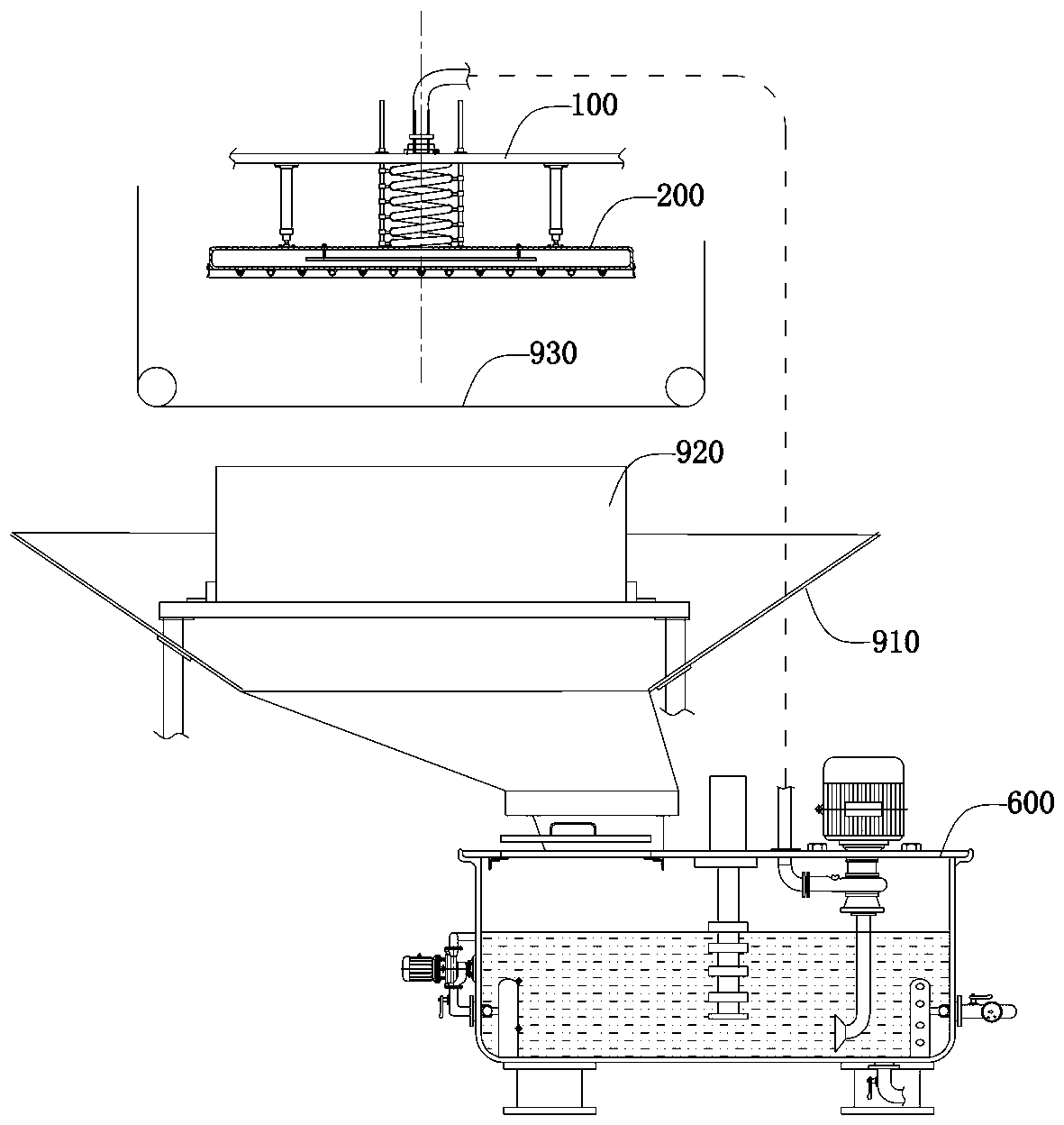
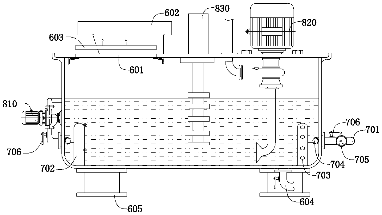
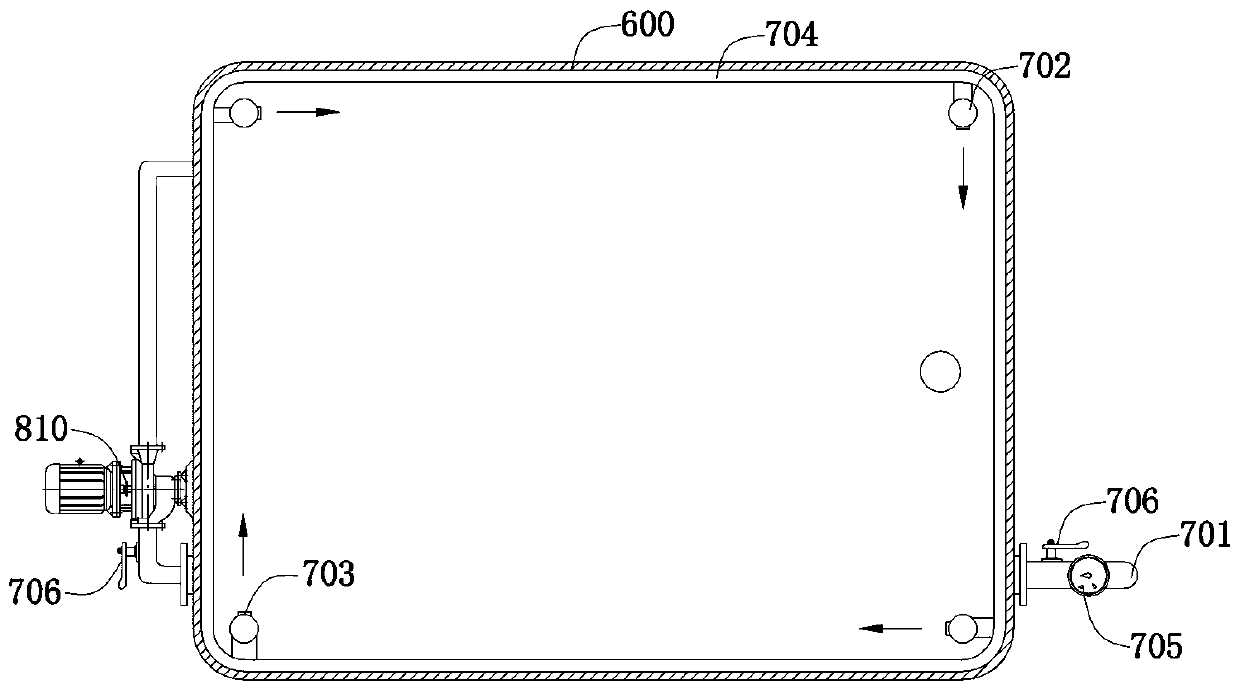
[0026] see Figure 1-Figure 6 , a mortar mixing and spraying system for a square cutter of the present invention, comprising a top bracket 100, a liquid supply tank 200, and a mortar mixing tank, the lower part of the liquid supply tank is provided with a lower edge plate 300, an air flow pipe 400 and an adjustable mortar The flow pipe 500 and the top bracket 100 are fixedly provided with a slurry supply pipe 101; between the liquid supply tank 200 and the top bracket 100, a lifting power push rod 102 and a telescopic tube 103 are arranged, and the telescopic tube 103 communicates with the liquid supply tank 200 and the supply tube. The slurry pipe 101, and the telescopic pipe 103 is in a spiral shape, and a guide slide bar 104 is arranged between the liquid supply tank 200 and the top support frame 100. The rod matches the sli...


PUM


Abstract

The invention belongs to the technical field of squarer and discloses a mortar stirring and spraying system for the squarer. The system comprises a top supporting frame, a liquid supply tank and a mortar stirring tank. A mortar supply pipe is fixedly arranged on the top supporting frame, and lifting power push rods and a telescopic pipe are arranged between the liquid supply tank and the top supporting frame. The mortar stirring tank comprises a tank body, a water supply pipe, a stirrer and a mortar pump, the water supply pipe, the stirrer and the mortar pump are arranged in the tank body, anda mortar outlet of the mortar pump is communicated with the mortar supply pipe. A lower edge plate, air flow pipes and adjustable mortar flow pipes are arranged at the bottom of the liquid supply tank. The system has advantages that a liquid film with a certain pressure can be formed on the surface of a silicon ingot and not only has permeation and dispersion effects but also forms a siphon effect to enable mortar to enter cutting seams under the driving action of a cutting line so as to achieve great cutting effects by interaction with the cutting line. Active mixing is realized through water supplying, self-circulation stirring is realized through a circulating water pump, and mortar stirring efficiency is greatly improved.

Description

technical field [0001] The invention belongs to the technical field of square cutting machines, and in particular relates to a mortar stirring and spraying system for square cutting machines. Background technique [0002] The square cutting machine is used for the block cutting of polycrystalline silicon ingots. Due to the unevenness of the upper end surface of the existing silicon ingots after casting, the traditional mortar nozzle cannot make sand adhere to the cutting line when spraying mortar on the cutting line. , resulting in the cut ingots being too large or too small, which cannot meet the production requirements. In addition, there are still some high-pressure nozzles in the prior art that force the mortar to appear uniformly foggy, but when the cutting line cuts into the silicon ingot, it cannot be formed Therefore, the cutting efficiency of the existing cutting wire is low, and the cutting quality is difficult to control. [0003] In addition, because the adequac...

Claims


Application Information

Patent Timeline
IPC IPC(8): B28D5/04B28D7/00
CPCY02P70/10
Inventor 刘勇翟军伟
Owner 河南省博宇新能源有限公司
Why Eureka
Try Eureka