Precise adjusting mechanism of spacing between rubber roller and steel roller during hot processing of light guide plate

A technology of adjusting mechanism and light guide plate, applied in printing presses, rotary printing presses, printing and other directions, can solve the problems of cursor induction interference, pressure climbing at the board seam, rubber roller damage, etc., to improve product yield and improve operability. sex, life expectancy

Active Publication Date: 2018-01-30
苏州盛诺邦自动化科技有限公司
View PDF6 Cites 5 Cited by
  • Summary
  • Abstract
  • Description
  • Claims
  • Application Information

AI Technical Summary

Problems solved by technology

[0004] 1. When there is no product material, if the rubber roller is pressed onto the steel roller by mistake, the high temperature of the steel roller will cause damage to the rubber roller and the mold;
[0005] 2. When producing under high temperature and high pressure, traces of plate grooves will be left on the product. If the traces are deep, it will interfere with the cursor induction of automatic die-cutting in the subsequent process;
[0006] 3. Due to the impact of the plate groove, the equipment will also produce periodic vibrations, which will affect the life of the rubber roller and product quality;
[0007]

Method used


Image

  • Precise adjusting mechanism of spacing between rubber roller and steel roller during hot processing of light guide plate
  • Precise adjusting mechanism of spacing between rubber roller and steel roller during hot processing of light guide plate
  • Precise adjusting mechanism of spacing between rubber roller and steel roller during hot processing of light guide plate

Examples


specific Embodiment approach

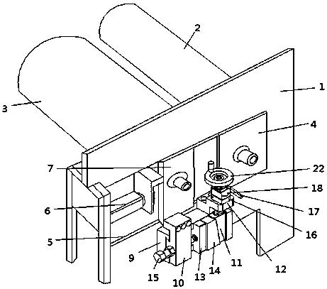
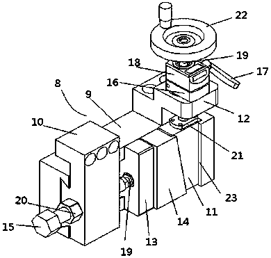
[0036] A specific embodiment of the present invention is as follows:

[0037] The alignment and zeroing process of the adjustment mechanism 8 before work: the dovetail groove 9 is fixed on the assembly frame 1, the rubber roller connecting block 10 is connected to the rubber roller slider 7, and after the rubber roller 3 or steel roller 2 is replaced on the frame 1, turn the hand The rocking wheel 22 resets the visual number in the position display 18 to zero to lower the first wedge block 11 to a certain position, twist the screw mandrel tightening handle 17 to drive the screw mandrel fixing splint 16 to lock the screw mandrel 19, and then connect the rubber roller slider 7 with the Cylinder 6 disengages, pushes the rubber roller 3 to contact the steel roller 2 so that the two are in close contact, at this time, rotate the adjusting screw 15 to make the zero adjustment block 13 push the second wedge block 14 into close contact with the first wedge block 11, then tighten the po...


PUM


Abstract

A precise adjusting mechanism of the spacing between a rubber roller and a steel roller during hot pressing of a light guide plate comprises a rack, the steel roller and the rubber roller. The steel roller is fixedly installed at one end of a sliding rail of the rack through a bearing pedestal, the rubber roller slides along the sliding rail through a rubber roller slider with one end connected with an air cylinder, and the precise adjusting mechanism further comprises adjusting mechanism bodies which are installed on the two sides of the rack respectively and used for precisely adjusting thespacing between the rubber roller and the steel roller. Each adjusting mechanism body comprises a dovetail groove fixedly formed in the rack, a rubber connecting block which is arranged at one end ofthe dovetail groove and fixedly connected with the rubber slider, a first wedge block which is arranged at the other end of the dovetail groove, and a screw rod installation base, wherein a zero-position adjusting block which slides along the sliding rail, and a second wedge block are arranged at the portion, between the rubber connecting block and the first wedge block, of the dovetail groove, and the first wedge block is connected with the screw rod installation base through a screw rod in the screw rod installation base. In the adjusting mechanism the spacing between the rubber roller and the steel roller during hot pressing of the light guide plate, the pressure adjusting mode is optimized, and the stability of a production technology is improved.

Description

technical field [0001] The invention relates to the field of auxiliary devices for heat-pressing transfer printing production equipment of a light guide plate, in particular to a mechanism for precisely adjusting the distance between a heat-pressing rubber roller and a steel roller of a light guide plate. Background technique [0002] At present, the core principle of the light guide plate hot-press transfer production equipment whose raw material is the optical film of the roll material is: two relatively rotating rollers, the transparent optical film passes between the rollers, and the temperature and pressure of the two rollers are applied to the rollers. The dots of the installed mold are printed on the optical film. The equipment used in the light guide plate production industry is basically fixed by a steel roller. The rubber roller is directly pushed onto the steel roller by means of an air cylinder or oil cylinder. The pressure is adjusted by air pressure or oil press...

Claims


Application Information

Patent Timeline
IPC IPC(8): B41F16/00
Inventor 张志锋
Owner 苏州盛诺邦自动化科技有限公司
Why Eureka
Try Eureka