Novel track layer for urban rail traffic engineering and its construction method

A technology of urban rail and traffic engineering, which is applied in the field of engineering technology and science, and can solve the problems of discontinuity, occupation, and impact of temporary running rails

Pending Publication Date: 2018-01-30
CHINA RAILWAY SHANGHAI ENGINEERING BUREAU GROUP CO LTD +1
View PDF10 Cites 10 Cited by
  • Summary
  • Abstract
  • Description
  • Claims
  • Application Information

AI Technical Summary

Problems solved by technology

Depending on the tunnel structure, the installation positions of the temporary running rails are also different (circular tunnels are installed on the side walls, horseshoe-shaped tunnels and rectangular tunnels are installed on the structural floor, and some structures require one side to be installed on the side wall and one side to be installed on the Structural floor), regardless of the installation method, will occupy the position space of the ballast bed structure, so that the concrete construction of the ballast bed will be completed from one time to two constructions (the integral ballast bed is poured first, and then the ballast bed ditch is poured), resulting in the formation of concrete between the ballast bed and the water ditch Structural joints; as the laying of the main line track continues to advance in a circular manner, a large number of temporary running rails are used in a circular manner, which affects the construction of the main line track both in terms of space and time; Drilling holes on the structure to fix the running rail pier will affect the appearance and performance of the structure to a certain extent. It is discontinuous, which not only occupies the installation position of the main line track, but also interrupts the construction work of the main line track due to the requirement of changing the span of the track laying machine, occupying the effective time and space of the track construction to varying degrees; due to the need to lay temporary running tracks, it increases the construction of the main line track. The operation process is shortened, the construction investment is increased, and the construction cost and labor intensity of personnel are increased.
[0003] In summary, although the existing track-laying machines for track construction are widely used in practical applications, they bring many constraints and influences to the construction of the main line

Method used


Image

  • Novel track layer for urban rail traffic engineering and its construction method
  • Novel track layer for urban rail traffic engineering and its construction method
  • Novel track layer for urban rail traffic engineering and its construction method

Examples


example 1

[0096] Example 1: Construction preparation, rail row lifting and installation of new track laying machine

[0097] 1. The new track laying machine changes from the running state to the rail row hoisting state

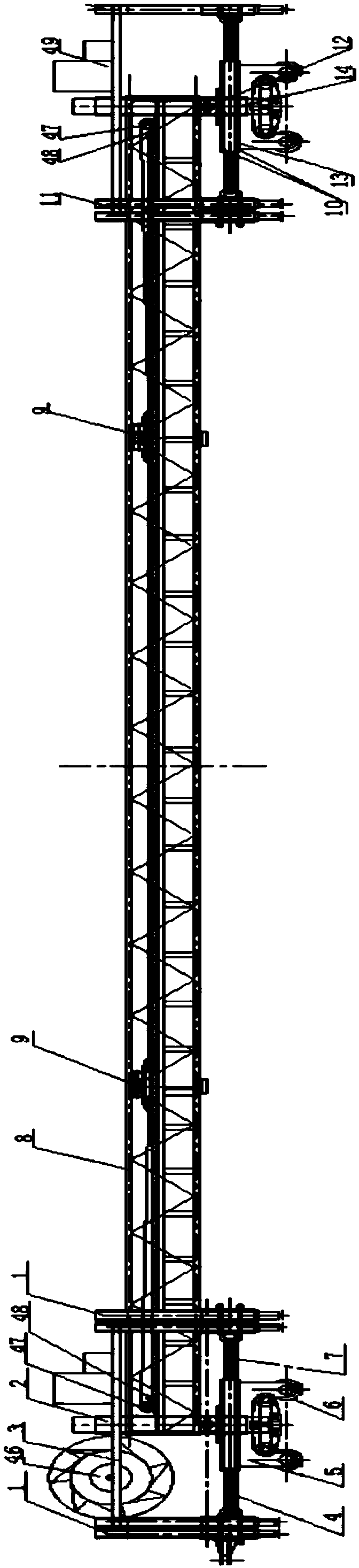
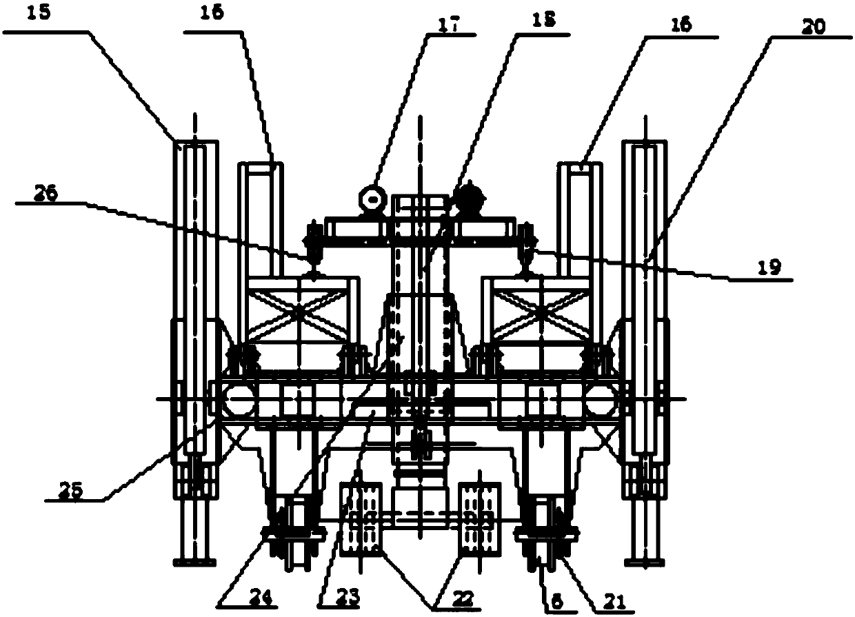
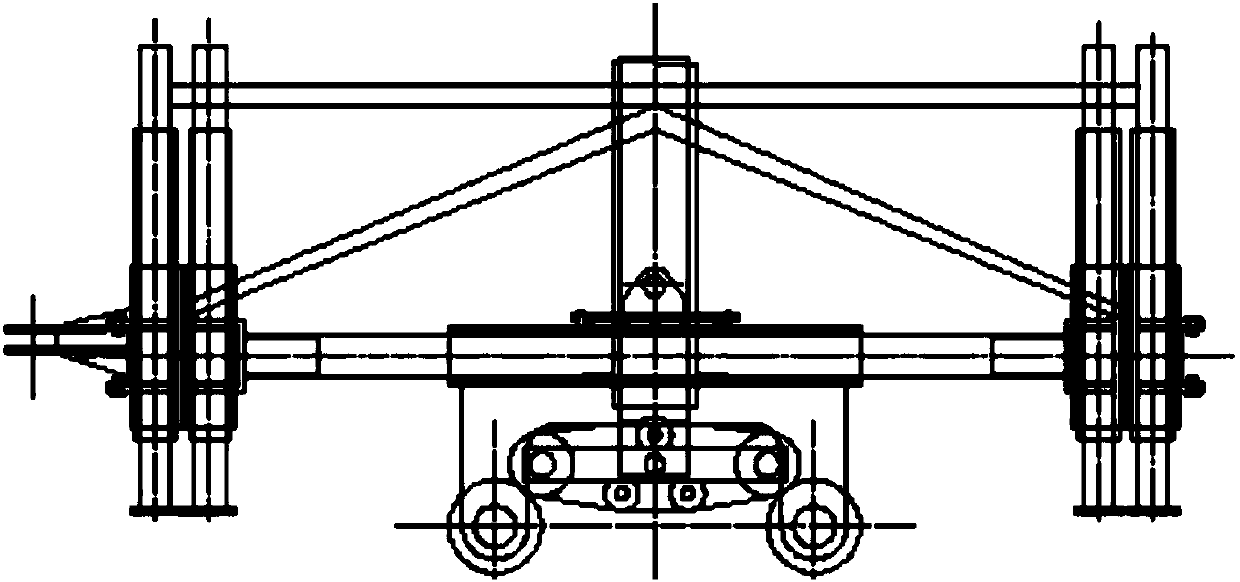
[0098] see Figure 1-6 , The main structural design of the present invention: the new track laying machine is composed of 2 lifting trolleys and connected hoisting truss beams.

[0099] see Figure 5-20 , the lifting traveling trolley is made up of a horizontal frame beam and a walking trolley, and the horizontal frame beam is made up of 2 longitudinal beams, 4 beams and an upper reinforcement structure (37). The 2 longitudinal beams are both the structural beams of the horizontal frame beam and the guide columns for the front and rear movement of the trolley, and the 4 cross beams are both the structural beams of the horizontal frame beam and the guide sleeve structure for the vertical support device of the lifting trolley to realize horizontal and lateral expansion ...

example 2

[0133] Example 2: Lifting and installation of prefabricated track slabs by new track laying machine

[0134] Urban rail transit track bed slab construction is generally carried out after the construction of the section track bed slab cushion is completed. The track bed slab is a prefabricated concrete slab, the length is generally 5800mm (common version), and the length of the curve adjustment plate is generally 4500mm-5000mm. In order to facilitate the prefabricated slab Transportation, generally after laying 25m-50m track bed slabs, install rail fasteners in time to form a transportation channel. When the track slab is laid over 100m, adjust the state of the track slab and the track, and pour self-compacting concrete or other mortar materials under the track slab. The track plate and the track state are fixed to form a track line. Therefore, laying track slabs is a key process.

[0135] 1. Track plate unloading, hoisting, moving and positioning

[0136] a. Lifting of new t...

example 3

[0156] Example 3: Transition of the working surface of the new track-laying machine

[0157] see Figure 20-37 , Track construction is generally centered on the track laying base, and the construction is carried out in both directions on the up and down lines. As the key equipment for track steering, the turnout is constructed in advance. The transfer of the working surface of the new track laying machine is realized by using the completed turnout and single crossing line. There are three positions for the working surface transfer, the new working surface 1, the new working surface 2 and the new working surface 3 on the way:

[0158] 1. Retract the horizontal telescopic device of the vertical support device of No. 1 and No. 2 lifting trolleys of the new track laying machine to the travel transfer position, and retract the vertical support device to the upper limit transfer travel position and lock it. Remove the power supply of the new track laying machine, and reel the cabl...


PUM


Abstract

The invention relates to the engineering technology science and particularly relates to a novel track layer for urban rail traffic engineering and its construction method. The device comprises a lifting walking work trolley, a connection truss beam, a track walking mechanism and a supporting structure; horizontal stretching and vertical supporting structures of the lifting walking trolley are operated firstly so as to lift the whole novel track layer to the height of a track hanging and dismounting material; a hoisting trolley lifts up the track material to leave a flat trunk and a material pad; the novel track layer is forwards walked to the installing position of a track section, and then the track material is dismounted; a steel track is connected and the track section is mounted to temporarily support and fix the newly installed track section; the track is walked towards the track section hoisting position in next time to arrive at the unloading place, then the track section is hoisted to the next cycle. The device is simple in structure, convenient to operate, and low in cost; meanwhile, the safety during the working process is ensured and the efficiency is improved.

Description

[technical field] [0001] The invention relates to engineering technology science, in particular to a new type of track laying machine for urban rail transit engineering and a construction method thereof. [Background technique] [0002] At present, in the track construction of urban rail transit projects in my country, the track-laying machine equipment used mainly includes three types: assembled fixed gate structure, manual and hydraulic fixed-distance variable-span gate structure, and automatic retrieval electric stepless variable-span gate structure. The track-laying machines of the three structural forms all need to lay temporary running rails for the track-laying machines to travel. Temporary running rails are pre-laid on the tunnel side wall or structural floor on both sides of the main line. The gauge is generally 2800mm, 3000mm, 3100mm, 3800mm, etc. The temporary running rails are fixed on the side of the tunnel by special steel structure piers wall or structural flo...

Claims


Application Information

Patent Timeline
Patent Type & Authority Applications(China)
IPC IPC(8): E01B29/16
CPCE01B29/16
Inventor 赵文君黄新郑康海韩建东孙军溪刘习生徐明发陈付平钱琨
Owner CHINA RAILWAY SHANGHAI ENGINEERING BUREAU GROUP CO LTD
Why Eureka
Try Eureka