Vernier type TDC circuit based on FPGA carry chain

A technology of carry chains and circuits, which is applied in the direction of electrical unknown time interval measurement, devices for measuring time intervals, clocks, etc., can solve the problems of uneven distribution of delays in delay units, uncontrollable and exacerbated non-uniformity, and reduce non-uniformity. Effects of linearity errors DNL and INL, reducing implementation complexity and resource overhead, and improving measurement accuracy

Active Publication Date: 2018-01-30
NANJING UNIV OF SCI & TECH
View PDF7 Cites 17 Cited by
  • Summary
  • Abstract
  • Description
  • Claims
  • Application Information

AI Technical Summary

Problems solved by technology

At present, most FPGA-based TDC technologies are implemented based on the carry chain and the tapped delay line scheme. The tap function can be realized by connecting a D flip-flop behind the delay unit and sampling the state of the delay unit. However, this scheme The non-linear performance is poor, and the DNL is generally at the level of ±1LSB, and some even reach several LSBs
In addition to the uneven distribution of the delay amount of the delay unit analyzed above, the reason for this phenomenon also includes the uneven distribution of the arrival delay of the sampling clock required by the D flip-flop in the clock network of the FPGA. This type of non-uniformity also uncontrollable
The degree of non-uniformity increases with the increase of the length of the delay line, which limits the dynamic range of this type of TDC measurement time, making the determination of TDC measurement accuracy and measurement range a contradiction. For example, a short delay line is easy to achieve higher measurement Accuracy, but its measurement range is smaller, and vice versa

Method used


Image

  • Vernier type TDC circuit based on FPGA carry chain
  • Vernier type TDC circuit based on FPGA carry chain
  • Vernier type TDC circuit based on FPGA carry chain

Examples


Embodiment 1

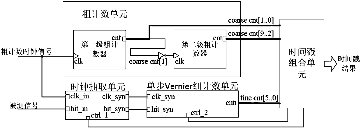
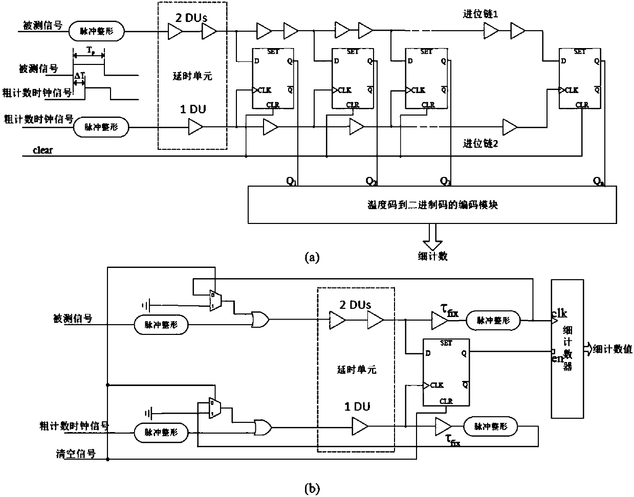
[0034] combine figure 1 , the present invention is based on the single-step Vernier type TDC circuit of FPGA delay chain, comprises coarse counting unit, single-step Vernier fine counting unit, clock extracting unit and time stamp combination unit, wherein coarse counting unit adopts two cascaded counters to improve coarse counting clock frequency. The values ​​of the two coarse counters are fed together into the timestamp combination unit as a result of the coarse time count. The single-step Vernier fine counting unit contains two delay lines composed of cascaded delay units of the carry chain. The output end of each delay line is returned to the input end of the delay line to form an oscillation loop. The two loops contain only 2 equivalent delay units (corresponding to slow delay lines) and 1 equivalent delay unit (corresponding to fast delay lines). The output end of the slow delay line is connected to the clock port of the fine counter to trigger the number of times the...


PUM


Abstract

The invention discloses a Vernier type TDC circuit based on an FPGA carry chain. The Vernier type TDC circuit comprises a coarse counting unit, a single-step Vernier fine counting unit, a clock extracting unit and a timestamp combining unit: the coarse counting unit is used for generating a coarse counting part in a timestamp result; the single-step Vernier fine counting unit is used for generating a fine counting part in the timestamp result, a slow delay line in the single-step Vernier fine counting unit is of a loop structure in which two equivalent basic delay units are included, and a quick delay line of the single-step Vernier fine counting unit is of a loop structure in which only one equivalent basic delay unit is included; the clock extracting unit is used for finding and searching for a coarse clock signal which occurs after a detected signal and the nearest to the detected signal; the timestamp combining unit is used for combining and outputting a complete timestamp result.The Vernier type TDC circuit solves the problem in he prior art that since a large quantity of delay units which are nonuniform in width distribution are utilized, the nonlinear error is large, and the measurement precision of a TDC is obviously improved.

Description

technical field [0001] The invention belongs to the technical field of digital measurement of time, in particular to a Vernier type TDC circuit based on FPGA carry chain. Background technique [0002] High-precision digital-to-time converter (TDC) was first developed from the field of high-energy particle measurement, and has now been extended to many other important application fields, such as nuclear medical imaging, radar, coincidence system, fully digital phase-locked loop and laser measurement. distance etc. Its basic task is to measure the time interval between two electrical pulse signals that have a sequence of arrival in time. From the perspective of implementation principles, the current mainstream methods include: a Vernier delay line scheme and a tapped delay line scheme. The Vernier delay line scheme includes two delay lines, and each delay line is composed of several delay units cascaded. The delays of the delay units belonging to different delay lines have ...

Claims


Application Information

Patent Timeline
Patent Type & Authority Applications(China)
IPC IPC(8): G04F10/00
Inventor 崔珂朱日宏任仲杰
Owner NANJING UNIV OF SCI & TECH
Why Eureka
Try Eureka