Circular antenna array design method for rotation circular polarization array element to produce OAM beam

A circular antenna and circularly polarized wave technology, applied in the field of wireless communication, can solve problems such as the complexity of the feeding network

Inactive Publication Date: 2018-01-30
CENT SOUTH UNIV
View PDF5 Cites 13 Cited by
  • Summary
  • Abstract
  • Description
  • Claims
  • Application Information

AI Technical Summary

Problems solved by technology

Therefore, it is necessary to design N phase shifters of different lengths, which will make the feed network more complicated

Method used


Image

  • Circular antenna array design method for rotation circular polarization array element to produce OAM beam
  • Circular antenna array design method for rotation circular polarization array element to produce OAM beam
  • Circular antenna array design method for rotation circular polarization array element to produce OAM beam

Examples


Embodiment 1

[0038] Using a circular array composed of 8 single-point fed circularly polarized microstrip antennas to rotate to generate OAM beams

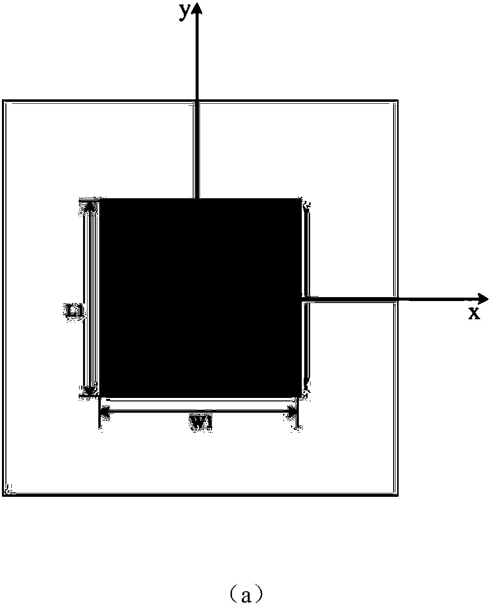
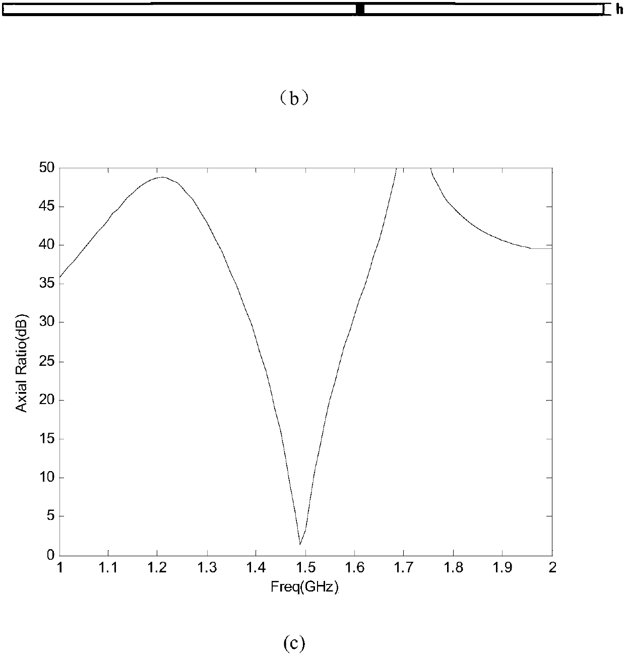
[0039] Step 1: Given the antenna center frequency f, determine and optimize the structure of a single array element to generate circularly polarized waves, so that the axial ratio of the circularly polarized waves at the center frequency is less than 3dB;

[0040] Let the antenna center frequency f be 1.5GHz, and the unit is set to generate right-handed circularly polarized waves. After calculation and simulation software optimization, the length of the rectangular radiation patch is L 1 =L 0 +a=47.31mm, width is W 1 =W 0 -a=45.98mm, where the initial dimension L 0 =W 0 =46.65mm, a=0.0143×L 0 . The material of the dielectric substrate is FR4 epoxy resin, and the height h=1.6mm. The distance between the feeding point and the x-axis and y-axis is d=8.85mm, and the radius of the coaxial feeder is 0.6mm. See the specific array element str...

Embodiment 2

[0049] OAM beams are generated by rotating a circular array composed of L-shaped probe orthogonal double-fed circularly polarized microstrip antennas

[0050] Step 1: Given the antenna center frequency f, determine and optimize the structure of a single array element to generate circularly polarized waves, so that the axial ratio of the circularly polarized waves at the center frequency is less than 3dB;

[0051] The antenna center frequency f is 2GHz. After calculation and simulation software optimization, the length and width of the square radiation patch are both taken as 46.65mm. The feeding point of the two L-shaped probes is directly below the midpoint of the two collar edges of the patch. The horizontal part points to the center of the patch, the vertical height is 13.8mm, the horizontal length is 17mm, the radius is 0.6mm, the material of the dielectric substrate is air, and the height is 20mm. See the specific structure Figure 4 (a)(b)(c), where, when the feeding me...


PUM

PropertyMeasurementUnit
Vertical heightaaaaaaaaaa
Horizontal lengthaaaaaaaaaa
Radiusaaaaaaaaaa

Abstract

The invention discloses a circular antenna array design method for a rotation circular polarization array element to produce an OAM beam. The design method comprises the steps that 1 the antenna center frequency f is given, and the structure of a single array element is determined and optimized to generate circular polarization waves; 2 N array elements determined in the step 1 are equidistantly arranged along the circumference into an initial uniform circular array antenna; 3 feed excitation of the same phase is carried out on each array element in an initial circular array, and codirectionalrotation at a specific angle is carried out to acquire a rotated circular antenna array; and 4 the radius of the circumference of the rotated circular antenna array is adjusted, so that the field phase diagram of the rotated circular antenna array presents a spiral phase wavefront and the OAM beam is produced to acquire the final circular antenna array. According to the invention, multiple phaseshifters of different lengths are not needed; the design of a feeding network is simplified; and a phase error introduced by each phase shifter is avoided.

Description

technical field [0001] The invention belongs to the field of wireless communication, and in particular relates to a design method of a circular antenna array for generating OAM beams. Background technique [0002] OAM (Orbital Angular Momentum, orbital angular momentum) beam, also known as vortex electromagnetic wave, is a special electromagnetic wave that carries OAM and has a helical phase wavefront. As we all know, due to the increasing demand for various communications, spectrum resources are becoming more and more scarce. In order to improve the utilization of spectrum resources, various multiplexing technologies have been invented. The earth broadens the ability to transmit signals. Therefore, OAM beams have received more and more attention and research in the field of communication in recent years. [0003] OAM beam generation methods mainly include helical parabolic antennas and circular antenna arrays with phase control. Compared with the helical parabolic antenna...

Claims


Application Information

Patent Timeline
IPC IPC(8): H01Q21/00H01Q1/50
Inventor 董健庄鑫姜泽锋邓联文
Owner CENT SOUTH UNIV
Why Eureka
Try Eureka