Self-thermal-insulation wall and manufacturing technology thereof

A self-insulation, wall technology, applied in covering/lining, construction, building structure, etc., can solve the problem that the bonding between foam concrete and cement pressure plate is not strong enough, the insulation effect of foam concrete is not ideal, and the service life of the wall is reduced, etc. problems, to achieve the effect of facilitating mechanized production, less mold support and mold removal processes, and saving templates

Active Publication Date: 2018-02-02
李寨真
View PDF11 Cites 7 Cited by
  • Summary
  • Abstract
  • Description
  • Claims
  • Application Information

AI Technical Summary

Problems solved by technology

[0003] The current formwork-free wall body uses cement pressure plates as templates alone, and a cavity is formed between the two cement pressure plates to pour foam concrete. Although the problem of form removal is solved, the thermal insulation effect of the foam concrete here is not ideal; and Because foam concrete is a cement product, it has low strength and some unstable factors. During the solidification and molding process of foam concrete, the expansion and shrinkage of foam concrete will cause certain damage to the integrity of the wall. After molding, foam concrete and The bonding between the cement pressure plates is not strong enough, and there are problems such as hollowing, which reduces the service life of the wall

Method used


Image

  • Self-thermal-insulation wall and manufacturing technology thereof
  • Self-thermal-insulation wall and manufacturing technology thereof
  • Self-thermal-insulation wall and manufacturing technology thereof

Examples


Embodiment Construction

[0044] Embodiments of the technical solutions of the present invention will be described in detail below in conjunction with the accompanying drawings. The following examples are only used to illustrate the technical solutions of the present invention more clearly, and therefore are only examples, rather than limiting the protection scope of the present invention.

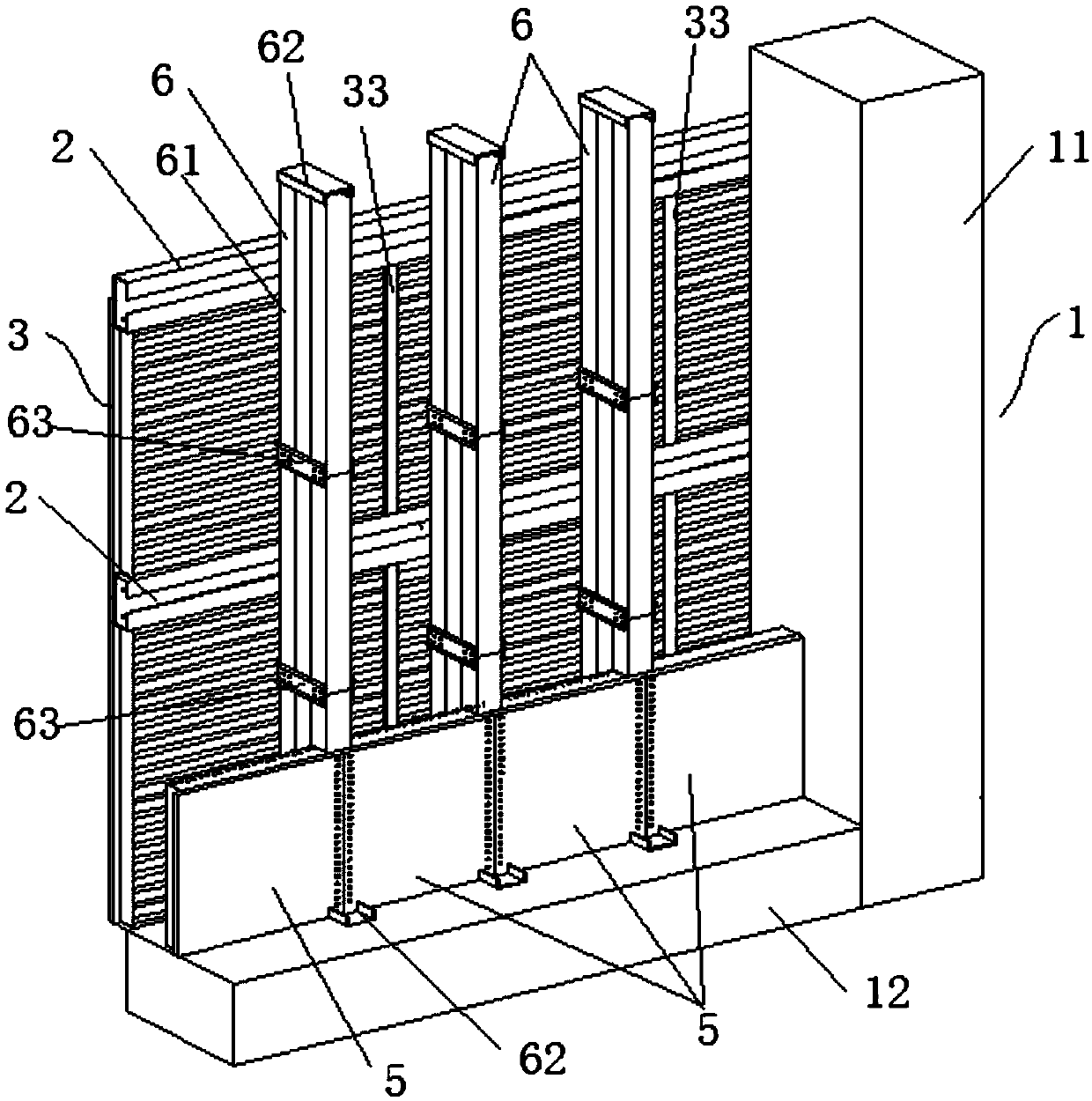
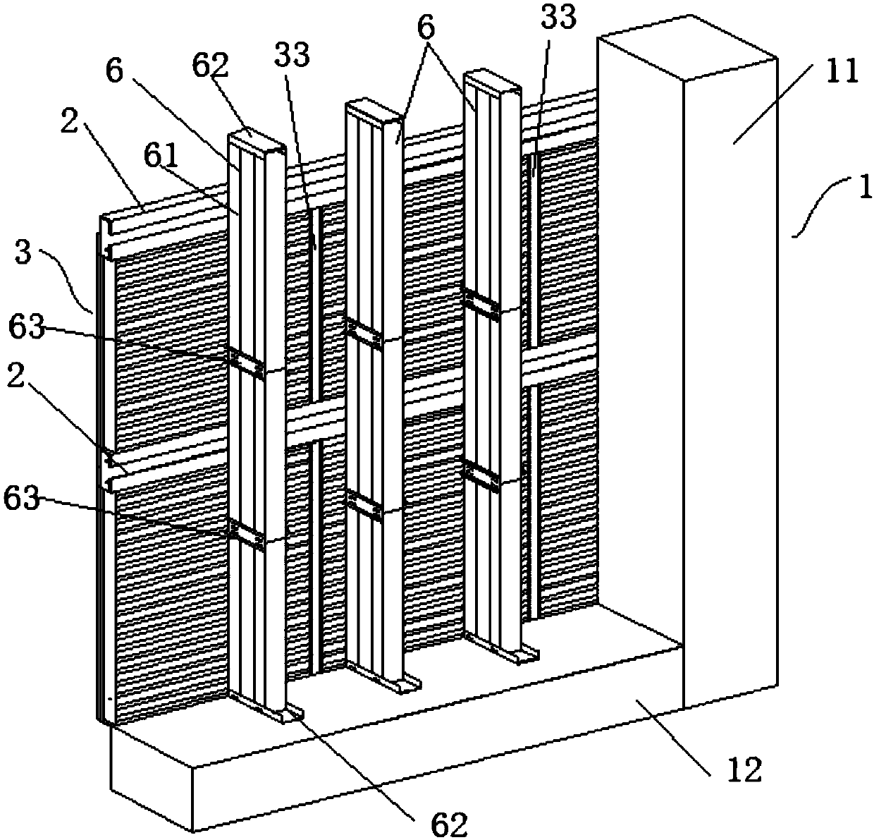
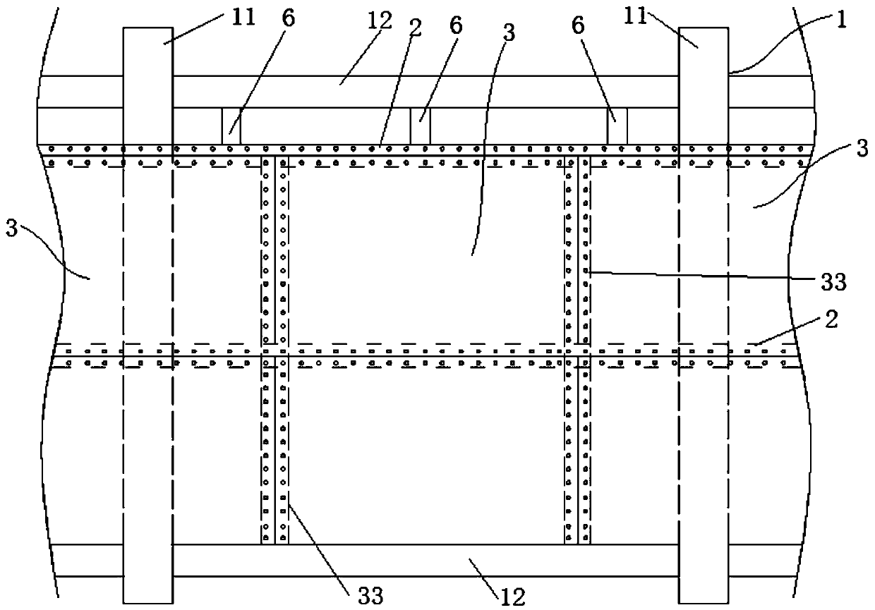
[0045] Such as Figure 1-Figure 7 The shown self-insulation wall includes a main body frame 1, a main keel 2, an outer insulation layer 3, an insulation core layer and an inner insulation layer 5; the outer insulation layer 3 and the inner insulation layer 5 are respectively arranged on both sides of the insulation core layer; The inner and outer insulation layers are prefabricated into blocks and then assembled.

[0046] The main frame 1 of this embodiment is a concrete frame, including vertically arranged structural columns 11 and horizontally arranged structural beams 12 between the structural columns 11; betwe...


PUM


Abstract

The invention provides a self-thermal-insulation wall and a manufacturing technology thereof. The self-thermal-insulation wall comprises a main body frame, a main keel, an outer thermal insulation layer, a thermal insulation core layer and an inner thermal insulation layer. The outer thermal insulation layer and the inner thermal insulation layer are arranged on the two sides of the thermal insulation core layer correspondingly, the outer thermal insulation layer comprises a first cement pressure plate and a dovetail groove polystyrene plate, the inner thermal insulation layer comprises a second cement pressure plate and a dovetail groove polystyrene plate, and the dovetail groove polystyrene plates are installed towards one side of the thermal insulation core layer; and the thermal insulation core layer is foam concrete, slurry of the foam concrete is poured to the position between the inner thermal insulation layer and the outer thermal insulation layer, and after forming, the slurryis connected with dovetail grooves in the dovetail groove polystyrene plates on the two sides in a buckled mode. According to the self-thermal-insulation wall, the mutually buckled connecting state is formed between the thermal insulation core layer prepared from the foam concrete and the dovetail groove polystyrene plates on the inner thermal insulation layer and the outer thermal insulation layer, connection is stable and firm, so that the thermal-insulation wall has good integrality, the thermal insulation performance is better, and the service life is longer.

Description

technical field [0001] The invention relates to the technical field of thermal insulation walls, in particular to a self-thermal insulation wall and a manufacturing process thereof. Background technique [0002] Cement pressure board, also known as fiber cement pressure board or cement fiber pressure board, is a new type of building board made of natural fiber and cement through pulping, molding, cutting, pressing and curing. Belonging to a new generation of "green" building materials, it has unique environmental protection functions on the basis of excellent moisture-proof and fire-proof performance. It is a new type of building material based on silicon and calcium materials as the main base material, cellulose fiber reinforced material, and other auxiliary materials, which are formed by copying and high-pressure curing. It has the advantages of light weight, high strength, waterproof, anti-corrosion, fire prevention, large format, good processability, and improved constr...

Claims


Application Information

Patent Timeline
Patent Type & Authority Applications(China)
IPC IPC(8): E04F13/075E04F13/22E04F13/24
CPCE04F13/0819E04F13/0875
Inventor 李寨真
Owner 李寨真
Why Eureka
Try Eureka