Supercharge Your Innovation With Domain-Expert AI Agents!

Automatic drainage system and method for centrifugal turbine compressor

A turbo compressor and automatic drainage technology, which is applied in the direction of machines/engines, mechanical equipment, radial flow pumps, etc., can solve the problem of secondary steam being easily atomized and condensed into water droplets, increasing the safety risk of manual operation, compressor components and Pipeline impact and other issues, to achieve the effect of flexible and adjustable drainage time and frequency, saving long-term maintenance costs, and avoiding the entry of external air

Pending Publication Date: 2018-02-02
深圳市宝安东江环保技术有限公司 +1
View PDF10 Cites 0 Cited by
  • Summary
  • Abstract
  • Description
  • Claims
  • Application Information

AI Technical Summary

Problems solved by technology

[0004] At present, the forced circulation evaporators used in the field of evaporation, concentration and crystallization need to compress and recirculate the secondary steam. Part of the secondary steam is easy to atomize and condense into water droplets, which will cause wear to the impeller; The bottom of the volute of the compressor is easily entrained by the high-speed and high-pressure airflow into the pipeline, which will affect the components and pipelines of the compressor
In addition, some enterprises abandon the traditional "oil" sealing form and adopt "air-water" mechanical seals. Although it can effectively prevent the condensed water and steam in the system from being polluted, the circulating cooling water of this type of mechanical seal also needs to be pumped from the worm gear. shell discharge
[0005] In the prior art, compressor manufacturers will install valves, and open the valves to drain water from time to time before and after the compressor is running. Due to the pressure changes inside and outside the compressor, this method will easily cause external air to enter the compressor. At the same time, this method also increases manual operations. The workload increases the safety risk of manual operation

Method used


Image

  • Automatic drainage system and method for centrifugal turbine compressor

Examples


Embodiment Construction

[0023] The present invention will be described in further detail below in conjunction with each accompanying drawing.

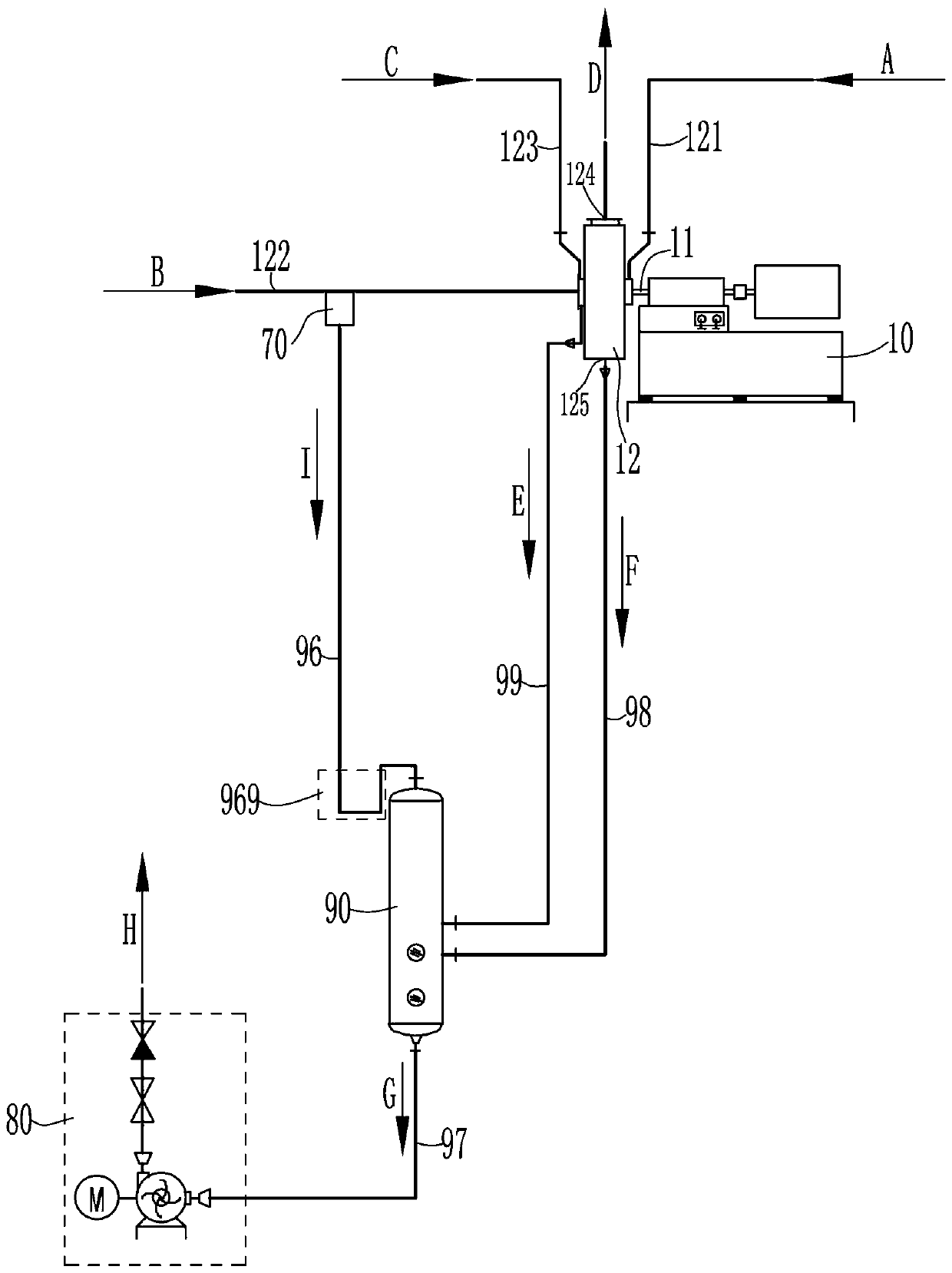
[0024] see figure 1 , an automatic drainage system for a centrifugal turbocompressor, comprising a centrifugal turbocompressor 10, a labyrinth seal ( Not shown, the specific structure of the labyrinth seal is the prior art, and will not be repeated here), the volute 12 is provided with a primary steam pipeline 121 for the primary steam to enter, and a secondary steam pipeline for the secondary steam to enter 122. The cooling water pipeline 123 for the cooling water to enter, the air outlet 124 for the secondary steam outlet, and the drain outlet 125 at the bottom for the accumulated water to be discharged; the automatic drainage system of the centrifugal turbocompressor also includes a drainage tank 90, a drainage pump 80 and the control circuit (not shown) for controlling the operation of the drainage pump 80; the condensate pipe 99 connects the drainage ta...


PUM


Abstract

The invention relates to an automatic drainage system and method for a centrifugal turbine compressor. The system comprises a centrifugal turbine compressor, a water drainage tank, a drainage pump anda control circuit, wherein labyrinth seal is adopted between a rotating shaft of the centrifugal turbine compressor and a volute of the centrifugal turbine compressor; a primary steam pipeline, a secondary steam pipeline, a cooling water pipeline, an air outlet and a water drainage port are arranged on the volute; the water draining tank communicates with the volute through a condensate water pipeline, so that condensate water in a labyrinth seal groove of the volute is discharged into the water drainage tank; the water accumulation pipeline is used for communicating the water drainage port at the bottom of the volute with the water drainage tank, so that accumulated water in the volute flows out of the volute and flows into the water drainage tank; a water outlet of the bottom of the water drainage tank communicates with the drainage pump through a main water outlet pipeline, and when the water storage amount in the water discharging tank reaches a set water level value, the controlcircuit enables the drainage pump to be started to work so as to empty water in the water drainage tank. The automatic drainage system for the centrifugal turbine compressor has the advantages of being easy to operate, safe, stable and good in quality.

Description

【Technical field】 [0001] The invention relates to a steam centrifugal compressor, in particular to an automatic drainage system for a centrifugal turbocompressor and a method for automatically draining the centrifugal turbocompressor. 【Background technique】 [0002] Turbine compressor is a dynamic compressor with high-speed rotating impeller. Its basic working principle is that the working wheel (referred to as impeller) with blades installed on the rotating shaft rotates at high speed under the drive of the driving machine. The gas inhaled between the blades of the impeller is thrown out at a high speed in a centrifugal form. During the process of being thrown out, the blades of the impeller do work on the gas to accelerate the gas and obtain kinetic energy. The kinetic energy is converted by deceleration through the diffusion flow. For pressure energy, thereby increasing the gas pressure; at the same time, the gas temperature is also increased accordingly; through multi-st...

Claims


Application Information

Patent Timeline
IPC IPC(8): F04D17/10F04D29/00F04D29/42
CPCF04D17/105F04D29/002F04D29/4206F04D29/706
Inventor 余雅旋彭运辉李春明龙雯
Owner 深圳市宝安东江环保技术有限公司
Features
  • R&D
  • Intellectual Property
  • Life Sciences
  • Materials
  • Tech Scout
  • Unparalleled Data Quality
  • Higher Quality Content
  • 60% Fewer Hallucinations
Learn More