
A measuring method using a measuring device

A measurement device and measurement method technology, applied in the field of measurement, can solve problems such as grid collision, grid probe damage, etc., and achieve the effect of avoiding collision and improving measurement speed.

Active Publication Date: 2020-02-07
CNNC JIANZHONG NUCLEAR FUEL +1
View PDF5 Cites 0 Cited by
  • Summary
  • Abstract
  • Description
  • Claims
  • Application Information

AI Technical Summary

Problems solved by technology

[0005] The primary purpose of the present invention is to solve the technical problem in the prior art that the measuring head will collide with the grid due to inaccurate positioning, resulting in damage to the grid or the measuring head

Method used


Image

  • A measuring method using a measuring device
  • A measuring method using a measuring device
  • A measuring method using a measuring device

Examples


Embodiment Construction

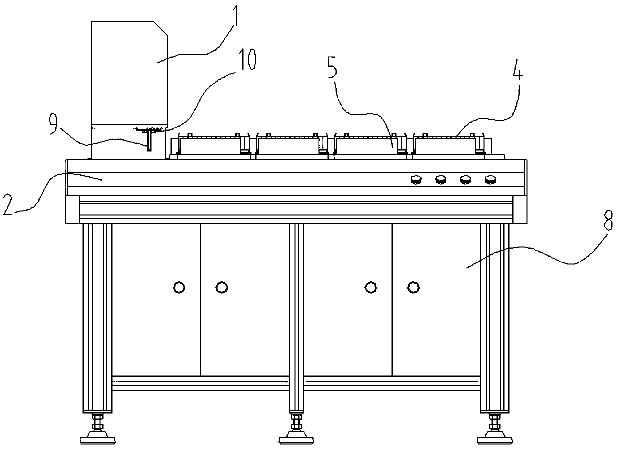
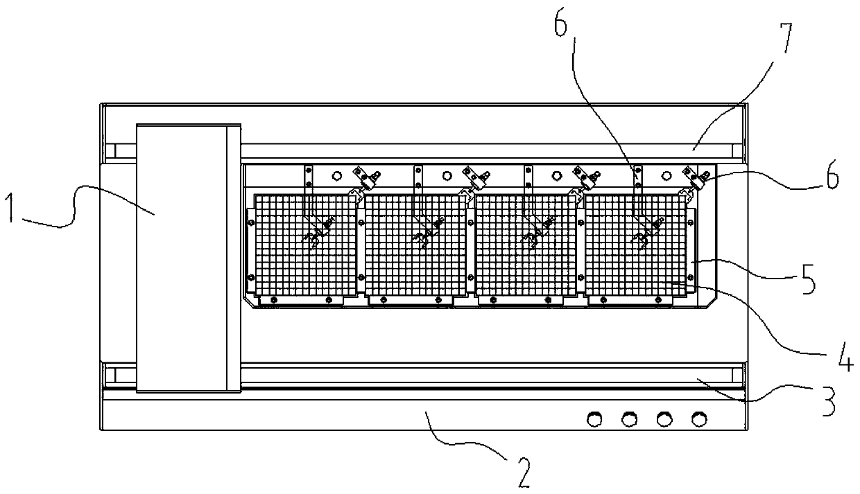
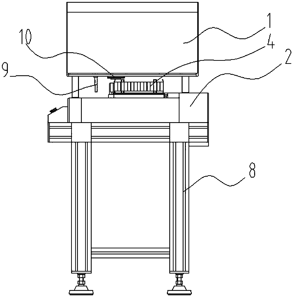
[0038] see Figure 1-3 , a measuring device with a probe positioning function, including a sliding trolley 1 and a workbench 2. On the workbench 2, a track I3 and a track II7 are arranged in parallel. The sliding trolley 1 can walk on the track I3 and the track II7 to measure Grid 4 cells at different positions. The measuring head 9 and the camera device 10 are installed on the sliding car 1 , and the measuring head 9 and the camera device 10 can move following the movement of the sliding car 1 . In this embodiment, the camera is selected as a CCD camera. Grid frame 4 is positioned on the workbench by positioning block 5, from figure 2 It can be seen that each grid frame 4 is positioned by three positioning blocks 5. In addition to being positioned by the positioning block 5, the grid frame 4 is also provided with a clamping mechanism 6, which is used to clamp the grid frame 4 so that it cannot move during the measurement process. In this embodiment, each grid frame 4 is ...


PUM


Abstract

The invention relates to the technical field of measurement. The invention discloses a measuring device with a measuring head positioning function. The measuring device comprises: a measuring head which is equipped with a strain gauge and a signal conversion device connected with the strain gauge; a worktable for placing lattices and a sliding trolley equipped with the measuring head, wherein theworktable is provided with a track allowing the sliding trolley to walk; a control module for controlling the walking of the trolley, an image processing module, a storage module and a display module.The sliding trolley is also provided with an imaging device, the imaging device is connected with the image processing module, the image processing module is connected with the storage module, the storage module is connected with the control module, and the control module is connected to the display module. The imaging device is used for rapid positioning before measurement, so that collision between the measuring head and lattices is prevented.

Description

technical field [0001] The invention relates to the field of measurement technology, in particular to a measurement method using a measurement device. Background technique [0002] In the nuclear industry, grids are needed to fix fuel rods, which requires very high clamping springs in the grid, that is, the clamping force should not be too large, if it is too large, nuclear leakage will easily occur, and it should not be too small. Otherwise, the fuel rod cannot be clamped. Therefore, before the grid is used, the clamping force of its spring must be tested. [0003] Chinese patent CN204301905U discloses an instrument for measuring the clamping force of the spring in the grid, which mainly uses strain gauges to detect the clamping force of the spring, and reads the data by the signal conversion module, thereby obtaining the clamping force of the spring . During the measurement process of this kind of measuring instrument, if the measurement is performed without prior posit...

Claims


Application Information

Patent Timeline
Patent Type & Authority Patents(China)
IPC IPC(8): G01L5/22G01L1/22G01C11/02
CPCG01C11/02G01L1/2206G01L5/22
Inventor 宋钢唐臻宇范元邓话于小焱黄洋张永乐陈宏伟盛建中王丹徐庆叶远东刘丽霞
Owner CNNC JIANZHONG NUCLEAR FUEL
Learn More