Battery pack monitoring system

A battery pack and monitoring system technology, applied in the direction of measuring electricity, measuring devices, measuring electrical variables, etc., can solve the problems of reducing the service life of battery packs, monitoring, battery pack failures, etc., to facilitate maintenance and management, reduce use costs, The effect of prolonging the service life

Inactive Publication Date: 2018-02-02
WUHAN AVIATION SENSING TECH
View PDF16 Cites 17 Cited by
  • Summary
  • Abstract
  • Description
  • Claims
  • Application Information

AI Technical Summary

Problems solved by technology

[0003] However, the chemical energy storage method of the single batteries in the battery pack is affected by various factors such as the environment and external power supply conditions, and some single batteries in the battery pack are in the standby state for a long time, so the performance changes of these single batteries are not easy to be detected. If it is discovered in time, it is likely to cause the battery pack to fail, unable to supply power to the forklift normally, and the forklift cannot work normally
[0004] The multiple battery packs in the forklift are used in an open manner. Users cannot monitor the cumulative charge and discharge times of each battery pack, nor can they monitor the current remaining power of each battery pack, charging temperature, and single battery cells in each battery pack. important data such as the electrolyte level, it is impossible to find out whether each battery pack fails in time
Due to the inability to effectively monitor each battery pack, the service life of each battery pack will be reduced. What is more serious is that due to the lack of effective monitoring and maintenance means, the status of each battery pack cannot be grasped in a timely and accurate manner, and the Hidden dangers when each battery pack fails

Method used


Image

  • Battery pack monitoring system
  • Battery pack monitoring system

Examples


Embodiment Construction

[0019] The specific implementation manners of the present invention will be further described in detail below in conjunction with the accompanying drawings and embodiments. The following examples are used to illustrate the present invention, but are not intended to limit the scope of the present invention.

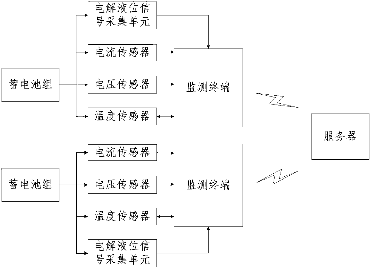
[0020] figure 1 It is a schematic structural diagram of a battery pack monitoring system according to an embodiment of the present invention, as shown in figure 1 As shown, the battery pack monitoring system includes: a server, a plurality of monitoring terminals and a plurality of data acquisition modules; for any battery pack in the plurality of battery packs, said any battery pack corresponds to a monitoring terminal and a data acquisition module , the data acquisition module includes a current sensor, a voltage sensor, a first temperature sensor and an electrolyte level signal acquisition unit; the current sensor is used to collect the current on the bus of any storag...


PUM


Abstract

The invention provides a battery pack monitoring system which mainly includes a server, multiple monitoring terminals, multiple sensor units, and a mobile phone APP. Each battery pack corresponds to one monitoring terminal and one external sensor unit. Each sensor unit includes a current sensor for collecting the current on the bus of the corresponding battery pack, a voltage sensor for collectingthe voltage on the bus of the corresponding battery pack, a temperature sensor for collecting the charging temperature on the surface of the corresponding battery pack, and an electrolyte level sensing unit for collecting the electrolyte level of the corresponding battery pack. Each monitoring terminal is used for collecting the signal of the corresponding external sensor unit and sending the current, voltage, charging temperature and electrolyte level of the corresponding battery pack to the server. The battery pack monitoring system can monitor each battery pack in a vehicle team. Thus, each battery pack can be effectively monitored, maintenance and management of battery packs are facilitated, the service life of battery packs is prolonged, the use safety of battery packs is improved, the use cost is reduced, and greater economic benefit is achieved.

Description

technical field [0001] The present invention relates to the field of batteries, and more specifically, to a battery monitoring system. Background technique [0002] At present, forklifts are often used in industrial handling, especially when loading and unloading, stacking and short-distance transportation of palletized goods. Forklifts use multiple battery packs for common power supply, and each battery pack is formed by connecting multiple single batteries. The reliability and stability of the battery pack and the tightness of the management of the battery pack are the guarantees for the normal operation of the forklift. As an important energy storage device and emergency uninterruptible power supply, the battery pack has the advantages of good reversibility, stable voltage characteristics, long service life, wide application range, and abundant raw materials, and has been widely used in various industries. [0003] However, the chemical energy storage method of the sing...

Claims


Application Information

Patent Timeline
Patent Type & Authority Applications(China)
IPC IPC(8): G01R31/36G01D21/02
CPCG01D21/02G01R31/371G01R31/392G01R31/396
Inventor 王林漆泽军张敏
Owner WUHAN AVIATION SENSING TECH
Why Eureka
Try Eureka