Smart home device having real point detection

A smart home, point detection technology, applied in the direction of instruments, computer control, comprehensive factory control, etc., can solve the problems of easy disasters, waste of electricity, and the processor home system cannot know the relay operation, etc., to ensure the safety of personnel.

Pending Publication Date: 2018-02-02
NANJING OHOSURE INTELLIGENT TECH CO LTD
View PDF0 Cites 0 Cited by
  • Summary
  • Abstract
  • Description
  • Claims
  • Application Information

AI Technical Summary

Problems solved by technology

[0003] Therefore, there will be the following problems during use: if the relay control circuit in the smart socket or switch is broken, and the corresponding action cannot be made after receiving the signal, the processor and home system still think that the control is successful, especially the remote control
And if the person controlling is not on site, the refusal of the relay will waste electricity and easily cause disasters
Or because of some objective reasons such as vibration, etc., the relay has actually acted, and the processor has not sent a signal, so the home system cannot know that the relay has operated.

Method used


Image

  • Smart home device having real point detection

Examples


Embodiment Construction

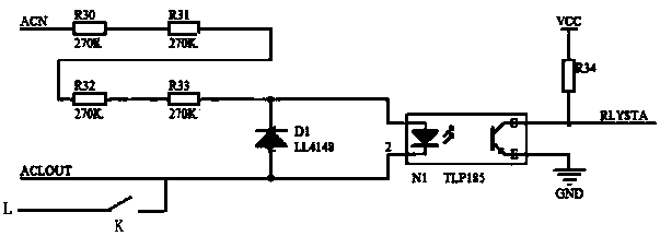
[0017] The present invention is described below in conjunction with accompanying drawing:

[0018] as attached figure 1 Shown is the real-point detection circuit diagram for detecting the relay circuit, in which the relay K is installed on figure 1 In the middle of L and ACLOUT, it specifically includes resistor R30, resistor R31, resistor R32, resistor R33, R34, diode D1 and photocoupler. Among them, R30, R31, R32, and R33 are four resistors connected in series in sequence. The optocoupler in the figure uses TLP185, the cathode of the optocoupler is used as the input terminal of the switching signal, the other end of R33 is connected to the anode of the optocoupler, and the diode D1 is connected between the cathode and the anode of the optocoupler. The emitter of the device is grounded, the collector of the photocoupler is connected to the microprocessor, one end of the resistor R34 is connected to the power supply VCC, and the other end is connected to the collector of the...


PUM


Abstract

The invention relates to the field of smart home, in particular to a smart home device with real point detection. A smart home control device with real-point detection, including a device body and a main control part connected to the device body; the main control part includes a single-chip microcomputer, a power circuit, a wireless communication circuit, and a relay circuit; the power circuit, wireless Both the communication circuit and the relay circuit are connected to the single-chip microcomputer; it is characterized in that: it also includes a real point detection circuit; one end of the real point detection circuit is connected to the output end of the relay in the relay circuit, and the other end is connected to the zero line of the alternating current; the real point The RLYSTA end of the detection circuit is connected with the microcontroller. In the present invention, when the state of the relay changes, the user can be reminded in time, so as to prevent the device from being actually shut down, waste electric energy, and increase the safety performance of the electrical appliance.

Description

technical field [0001] The invention relates to the field of smart home, in particular to a smart home device with real point detection. Background technique [0002] Nowadays, with more and more types of home appliances that can be purchased by Chinese households, the intelligentization of household electrical products has become a trend. As an important member of smart home appliances, smart socket and smart switch have been widely popularized. When the current smart switch of the smart socket receives a remote control command, the processor will send a signal to the electrical control circuit in the socket or the switch and accordingly consider that the relay contact is switched successfully. [0003] Therefore, there will be the following problems during use: if the relay control circuit in the smart socket or switch is broken, and the corresponding action cannot be made after receiving the signal, the processor and home system still think that the control is successful...

Claims


Application Information

Patent Timeline
Patent Type & Authority Applications(China)
IPC IPC(8): G05B15/02G05B19/418
CPCG05B15/02G05B19/418G05B2219/2642
Inventor 韩大鹏林巍鲁春军
Owner NANJING OHOSURE INTELLIGENT TECH CO LTD
Why Eureka
Try Eureka